I.9 parameter table – Yaskawa iQpump Micro Quick Start User Manual
Page 95
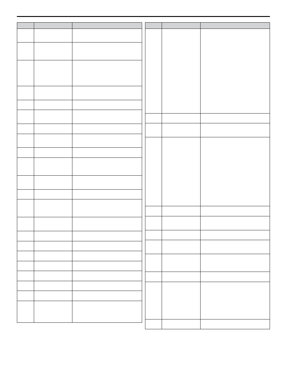
No.
Name
Description
L3-20
DC Bus Voltage
Adjustment Gain
Sets the proportional gain for KEB Ride-
Thru, Stall Prevention, and overvoltage
suppression.
L3-21
Accel/Decel Rate
Calculation Gain
Sets the proportional gain used to calculate
the deceleration rate during KEB Ride-
Thru, ov suppression function, and Stall
Prevention during deceleration (L3-04 = 2).
L3-23
Automatic Reduction
Selection for Stall
Prevention during Run
0: Sets the Stall Prevention level set in
L3-06 that is used throughout the entire
frequency range.
1: Automatic Stall Prevention level
reduction in the constant output range. The
lower limit value is 40% of L3-06.
L3-24
Motor Acceleration
Time for Inertia
Calculations
Sets the time needed to accelerate the
uncoupled motor at rated torque from stop
to the maximum frequency.
L3-25
Load Inertia Ratio
Sets the ratio between the motor and
machine inertia.
L4-01
Speed Agreement
Detection Level
L4-01 sets the frequency detection level for
digital output functions H2-oo = 2, 3, 4,
5.
L4-02
Speed Agreement
Detection Width
L4-02 sets the hysteresis or allowable
margin for speed detection.
L4-03
Speed Agreement
Detection Level (+/-)
L4-03 sets the frequency detection level for
digital output functions H2-oo = 13, 14,
15, 16.
L4-04
Speed Agreement
Detection Width (+/-)
L4-04 sets the hysteresis or allowable
margin for speed detection.
L4-05
Frequency Reference
Loss Detection
Selection
0: Stop. Drive stops when the frequency
reference is lost.
1: Run. Drive runs at a reduced speed when
the frequency reference is lost.
L4-06
Frequency Reference
at Reference Loss
Sets the percentage of the frequency
reference that the drive should run with
when the frequency reference is lost.
L4-07
Speed Agreement
Detection Selection
0: No detection during baseblock.
1: Detection always enabled.
L5-01
Number of Auto
Restart Attempts
Sets the number of times the drive may
attempt to restart after the following faults
occur: GF, LF, oC, oH1, ov, PF, rH, rr, oL1,
oL2, oL3, oL4, STo, Uv1.
L5-02
Auto Restart Fault
Output Operation
Selection
0: Fault output not active.
1: Fault output active during restart attempt.
L5-04
Fault Reset Interval
Time
Sets the amount of time to wait between
performing fault restarts.
L5-40
Low Feedback Fault
Retry Selection
0: No retry
1: Retry
L5-41
High Feedback Fault
Retry Selection
0: No retry
1: Retry
L5-42
Feedback Loss Fault
Retry Selection
0: No retry
1: Retry
L5-50
Setpoint Not Met Retry
Selection
0: No retry
1: Retry
L5-51
Loss of Prime Fault
Retry Selection
0: No retry
1: Retry
L5-52
Pump Over Cycle Fault
Retry Selection
0: No retry
1: Retry
L5-53
Volute-TStat Retry
Selection
0: No retry
1: Retry
Note: The drive will restart only after the
Volute-Tstat digital input deactivates and
the L5-04 timer expires.
No.
Name
Description
L6-01
Torque Detection
Selection 1
0: Disabled
1: oL3 detection only active during speed
agree, operation continues after detection
2: oL3 detection always active during run,
operation continues after detection
3: oL3 detection only active during speed
agree, output shuts down on an oL3 fault
4: oL3 detection always active during run,
output shuts down on an oL3 fault
5: UL3 detection only active during speed
agree, operation continues after detection
6: UL3 detection always active during run,
operation continues after detection
7: UL3 detection only active during speed
agree, output shuts down on an oL3 fault
8: UL3 detection always active during run,
output shuts down on an oL3 fault
9: UL6 Alarm at Speed Agree
10: UL6 Alarm during Run
11: UL6 Fault at Speed Agree
12: UL6 Fault during Run
L6-02
Torque Detection
Level 1
Sets the overtorque and undertorque
detection level.
L6-03
Torque Detection Time
1
Sets the time an overtorque or undertorque
condition must exist to trigger torque
detection 1.
L6-04
Torque Detection
Selection 2
0: Disabled
1: oL4 detection only active during speed
agree, operation continues after detection
2: oL4 detection always active during run,
operation continues after detection
3: oL4 detection only active during speed
agree, output shuts down on an oL4 fault
4: oL4 detection always active during run,
output shuts down on an oL4 fault
5: UL4 detection only active during speed
agree, operation continues after detection
6: UL4 detection always active during run,
operation continues after detection
7: UL4 detection only active during speed
agree, output shuts down on an oL4 fault
8: UL4 detection always active during run,
output shuts down on an oL4 fault
L6-05
Torque Detection
Level 2
Sets the overtorque and undertorque
detection level.
L6-06
Torque Detection
Time 2
Sets the time an overtorque or undertorque
condition must exist to trigger torque
detection 2.
L6-13
Motor Underload
Protection Selection
0: Base frequency enable
1: Max frequency enable
L6-14
Motor Underload
Protection Level at
Minimum Frequency
Sets the UL6 detection level at minimum
frequency by percentage of drive rated
current.
L8-01
Internal Dynamic
Braking Resistor
Protection Selection
(ERF type)
0: Resistor overheat protection disabled
1: Resistor overheat protection enabled
L8-02
Overheat Alarm Level An overheat alarm occurs when heatsink
temperature exceeds the L8-02 level.
L8-03
Overheat Pre-Alarm
Operation Selection
0: Ramp to stop. A fault is triggered.
1: Coast to stop. A fault is triggered.
2: Fast Stop. Decelerate to stop using the
deceleration time in C1-09. A fault is
triggered.
3: Continue operation. An alarm is
triggered.
4: Continue operation at reduced speed as
set in L8-19.
L8-05
Input Phase Loss
Protection Selection
0: Disabled
1: Enabled
i.9 Parameter Table
YASKAWA TOEP YAIQPM 02B YASKAWA AC Drive - iQpump Micro Quick Start Guide
95