Smart trac ac1 – Yaskawa SmartTrac AC1 User Manual
Page 32
SMART TRAC AC1
4-12
••
Smart Trac AC1 Installation Technical Manual TM 3554-000
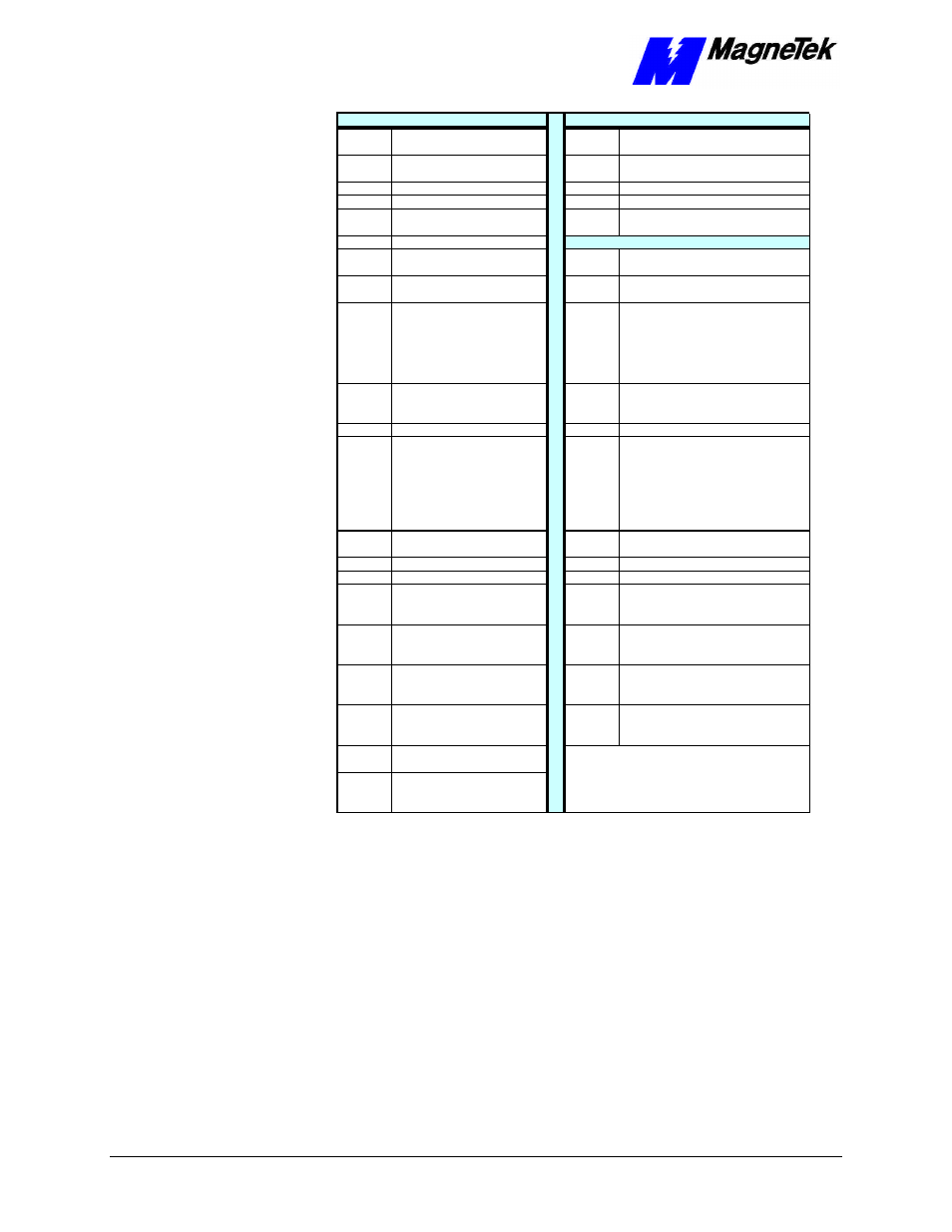
Term No.
Function
Term No.
Function
1*
Multifunction Logic Input 1
23
Multifunction Analog Output 2, 0 to +11
V; 2mA maximum
2*
Multifunction Logic Input 2
25
Open-collector Output: +48 V, 50 mA
maximum
3*
Multifunction Logic Input 3
26
Open-collector Output
4*
Multifunction Logic Input 4
27
Multifunction Open C ollector Common
5*
Multifunction Logic Input 5
33
-15 VDC Contro l power supply for
frequency settins: 20 mA max
6*
Multifunction Logic Input 6
POWER CONNECTIONS
7*
Multifunction Logic Input 7
L
1-phase power 90-264 V, to Smart
Trac PS
8*
Multifunction Logic Input 8
N
1-phase power 90-264 V, to Smart
Trac PS
9, 10
Multifunction contact output
(N.O.) One of 18 functions
available by setting of
parameter H2-01 . Contact
capacity: 250 VAC at 1A or
less; or 30 VDC at 1A or less
L1
3-phase power 230 V/460 V
11
COM, sequence control input
common fo r terminals 1-6, 0 V
L2
3-phase power 230 V/460 V
12
Shield sheath of signal leads
L3
3-phase power 230 V/460 V
13
Typically Speed Reference, but
is mu ltifunction analog input: 0
V to +10V (20K ohms), -10 V to
+10V (20K ohms), Can be
changed to manual by setting
of parameter H3-01.
T1
Motor
14
Analog Input 2, 4-20mA (250
ohms)
T2
Motor
15
+15 VDC
T3
Motor
16
Analog Input 1
B1
Dynamic Braking (option)
17
Multifunction Analog Input
Common, 0 V for termina ls 13
thru 16, and 33
B2
Dynamic Braking (option)
18
Fault Contact-OPEN, capacity:
250 VAC at 1A or less or 30
VDC a t 1A or less
+1
DC Reactor (option)
19
Fault Contact-OPEN, capacity:
250 VAC at 1A; or less or 30
VDC a t 1A or less
+2
DC Reactor (option)
20
Fault Contact-OPEN, capacity:
250 VAC at 1A; or less or 30
VDC a t 1A or less
9-pin D
connector Isolated RS-232
21
Mutlifunction Analog Output 1,
0 to +11 V; 2mA maximum
22
Multifunction Analog Output
Common for termina ls 21 and
23, 0 to +11V; 2mA max.
* NOTE: Terminals 1-8 source +24 VDC (8MA
max), Low=True (ON) when conne cted to terminal
11
Table 6.
Terminal Definitions of the Inverter Control Card
Make connections according to the "Simplified Customer Connection Diagram"
with the following notes:
Do not exceed 164 feet (50 meters).
Consider voltage drop when determining size.
Consult "Table 3. Wire Sizing for
Main Circuit, 230 Volt" on page 6, "Table 4. Wire Sizing for Main Circuit, 460
Volt" on page 7, "Table 5. Wire Sizing for Main Circuit 600V (575V)." on page
9.
Terminal Definitions of
the Inverter Control
Card
Connections
Lead Length:
Wire Sizes: