Yaskawa SmartTrac AC1 User Manual
Page 66
SMART TRAC AC1
7-4
••
Smart Trac AC1 Maintenance Technical Manual TM 3554-000
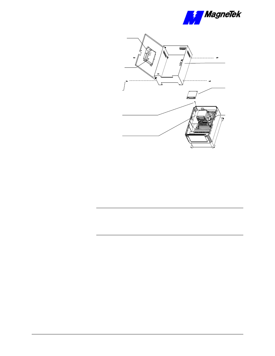
12-pin wiring
harness on
Digital Operator
attached to
connector J4 on
Smart Trac
CPU Card
Digital
Operator
4mm screws
(4 places)
secure ring
to main
chassis
Standoffs (4
places)
secure each
board
Smart Trac
Board Stack
9-pin RS-232
cable
connector J5
PC/104
board
9-pin RS-232
cable
attached here
Figure 13. Removing the Smart Trac Card Stack
9. Continue removing all PC/104 cards, including option, Smart Trac
Ethernet and Smart Trac PS cards, using steps 8 and 9.
10. To remove the Smart Trac PG card:
•
Disconnect the 4CN Connector cable on the PG card.
•
Remove the card.
NOTE: The PG card requires unique handling. Wedge the extracting tool
between the PG card and the CPU card. The area between the terminal strip on
the CPU card and the serial numbered edge of the PG card can be lifted first,
then the opposite side (nearest TB1 on the PG card). Alternate sides until the
card is free of the CPU card.
11. To remove the Smart Trac CPU card:
•
Locate the black 2CN connector between the Smart Trac CPU card
and the Inverter Control card.
•
The CPU card is secured with three plastic standoffs with spring-
loaded clips on the end. Squeeze the top of the standoffs (the clips)
with the special cylindrical removal tool, your fingers or needle-
nosed pliers and lift the CPU card from the Smart Trac Inverter
Control Card.
•
Remove the Smart Trac CPU card. Be very careful when lifting not
to bend connecting pins at the 2CN connector.
12. To remove the Smart Trac Inverter Control Card (1PCB):
•
Disconnect the wiring harness at connector 7CN, located at the top
of the card.