Yaskawa SmartTrac AC1 User Manual
Page 39
SMART TRAC AC1
Technical Manual TM 3554-000 Smart Trac AC1 Installation
••
4-19
19. Disconnect the ribbon cable or wiring harness attached to the Digital
Operator from connector PCB 1CN.
20. Connect the Digital Operator to its normal location on connector J4 on
the Smart Trac CPU card.
21. Power up the drive.
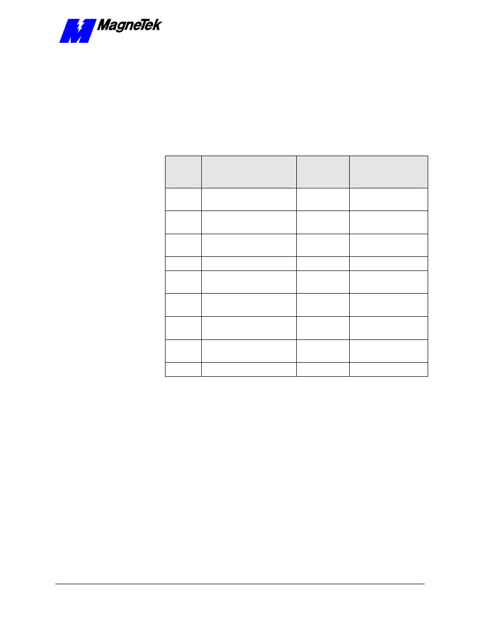
22. Load parameters as follows:
Table 7.
Motor Setup Parameters
Para-
meter
Description
Numeric
Parameter
Number
Displayed
Description
E2-01
Motor rated current
48
RATED MOTOR
AMPS
E2-02
Motor rated slip
47
MOTOR RATED
SLIP
E2-03
Motor no-load current
49
MTR NO LOAD
AMPS
E2-04
Number of motor poles
50
MOTOR POLES
E2-05
Motor line-to-line
resistance
51
MTR TERM RES.
E2-06
Motor leakage inductance
52
MTR LEAKAGE
IND.
E2-07
Motor iron core saturation
coefficient 1
53
MTR SAT COEF 1
E2-08
Motor iron core saturation
coefficient 2
54
MTR SAT COEF 2
E2-09
Motor mechanical loss
55
MTR MECH LOSS