Pre-power checklist – Yaskawa SmartTrac AC1 User Manual
Page 33
SMART TRAC AC1
Technical Manual TM 3554-000 Smart Trac AC1 Installation
••
4-13
NOTE: Signal and Control Leads require twisted-pair shielded wire (20-16
AWG [0.5 – 1.25mm
2
]). Shield sheath terminal 12 requires twisted shielded
or twisted-pair shielded wire (20-14 AWG [0.5 – 2.0mm
2
]).
•
Multifunction Logic Inputs to Terminals 1 thru 8 and 11.
•
Multifunction Analog Inputs to Terminals 12 thru 17, 33.
•
Multifunction Analog Outputs to Terminals 21 thru 23.
•
Multifunction Open-collector Outputs to Terminals 25 thru 27.
•
Multifunction Contacts to Terminals 9 and 10.
•
Fault Contacts to Terminals 18, 19 and 20.
•
Single Phase Power 90-264 V to Terminals L and N.
•
Three Phase Power 230V/460V to Terminals L1, L2 and L3.
•
Motor (Output) to Terminals T1, T2 and T3.
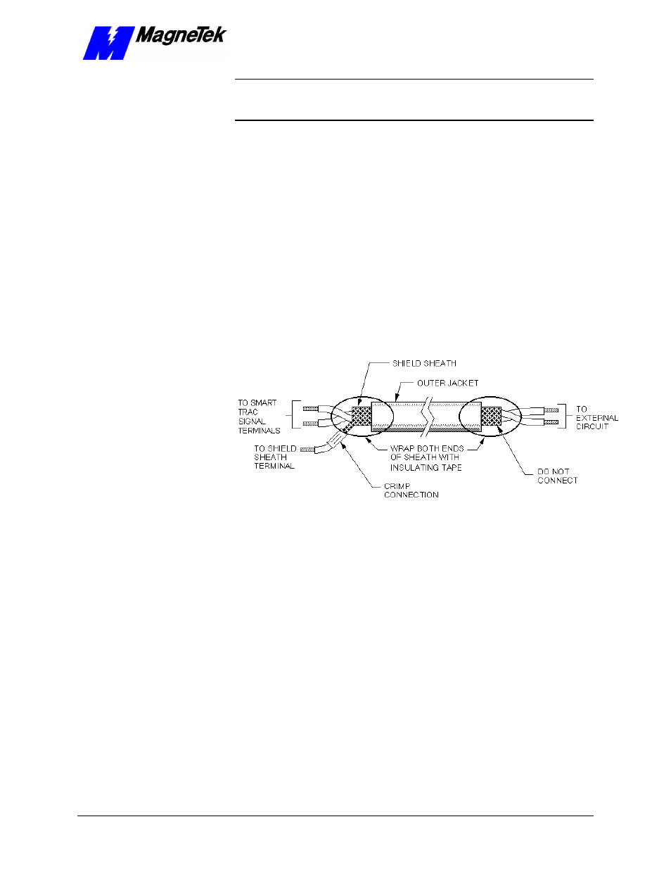
Terminate woven metallic shielded cables at only one end, typically at the
power supply end, as shown
"Figure 4. Shielded Termination" on page 16.
When using foil type shields, terminate the drain wire in a similar manner.
Figure 4.
Shielded Termination
The Optional Smart Trac PG (Pulse Generator) card, Arcnet card and other
cards are described in separate, specific manuals. See the specific manual for
appropriate connection information.
Pre-Power Checklist
q
Verify wires are properly connected and no erroneous grounds exist.
q
Ensure all debris is removed from the Smart Trac enclosure and there are no
loose wire clippings.
q
Verify cooling fans are free of debris and rotate freely.
q
Verify all electrical and mechanical connections for the Smart Trac AC1 are
present and tighten, as necessary
q
Verify and test source power is correct for the drive installed.
Signal Leads:
Control Leads:
Power Leads:
Terminating Shielded
Cable
Connecting Optional
Cards