Mounting hardware and hole dimensions, Smart trac ac1 – Yaskawa SmartTrac AC1 User Manual
Page 72
SMART TRAC AC1
8-2
••
Appendix A – Dimensions Technical Manual TM 3554-000
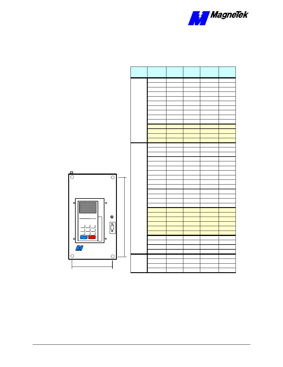
Mounting Hardware and Hole
Dimensions
RUN
STOP
MagneTek
Mounting Hole
Width
Mounting Hole Height
Input Volts
Continuous
Output Amps
1
Nominal
HP
2
Mounting
Screws
Mounting
Hole Height
(in.)
Mounting
Hole Width
(in.)
3.2
3/4
#10
10.47
4.96
6
1
#10
10.47
4.96
8
2
#10
10.47
4.96
11
3
#10
10.47
4.96
17.5
5
#10
10.47
4.96
25
7.5
1/4"
11.22
7.32
33
10
1/4"
11.22
7.32
49
15
1/4"
14.37
9.29
64
20
1/4"
14.37
9.29
80
25/30
1/4"
17.13
10.83
130
40/50
1/4"
25.59
12.60
160
60
1/4"
25.59
12.60
224
75
3/8"
30.51
14.57
300
100
3/8"
35.24
17.52
1.8
1
#10
10.47
4.96
3.4
2
#10
10.47
4.96
4.8
3
#10
10.47
4.96
8
5
#10
10.47
4.96
11
7.5
#10
10.47
4.96
14
10
1/4"
11.22
7.32
21
15
1/4"
11.22
7.32
27
20
1/4"
14.37
9.29
34
25
1/4"
14.37
9.29
41
30
1/4"
17.13
10.83
52
40
1/4"
17.13
10.83
65
50
1/4"
24.02
10.83
80
60
1/4"
24.02
10.83
96
75
1/4"
24.02
10.83
128
100
3/8"
31.30
13.78
165
125
3/8"
31.30
13.78
224
150
3/8"
35.24
17.52
302
200/250
3/8"
35.24
17.52
450
300/350
3/8"-16
55.12
*
605
400/500
3/8"-16
31.02
*
400A
-
800A
-
1200A
-
1600A
-
400A
-
800A
-
1200A
-
1600A
-
2
3
0
V
4
6
0
V
6
0
0
V