ProSoft Technology MVI56E-MCM/MCMXT User Manual
Page 42
Configuration as a Modbus Master
MVI56E-MCM ♦ ControlLogix Platform
User Manual
Modbus Communication Module
Page 42 of 199
ProSoft Technology, Inc.
June 18, 2014
Label
Description
Enable = 1
The module will send the command every time it goes through the
command list.
IntAddress = 1000
Places the data read from the Slave device into the module at address
1000. IntAddress 1000 of the module memory will be copied into the tag
MCM.DATA.R
EAD
D
ATA
[0].
Count = 10
Reads 10 consecutive registers from the Slave device.
Node = 1
Issues the Modbus command to node 1 on the network.
Func = 3
Issues Modbus Function Code 3 to Read Holding Registers.
DevAddress = 0
Function Code 3, DevAddress of 0 will read address 40001
Along with a count of 10, this command reads 40001 to 40010.
2.3.2 Read Input Registers 3x (Modbus Function Code 4)
Like the 4x holding registers, 3x input registers are used for reading analog
values that are 16-bit register values. You can also use these registers to store
Floating-Point Data Handling (Modbus Master) (page 46). Unlike the 4x registers,
3x registers are Read Only.
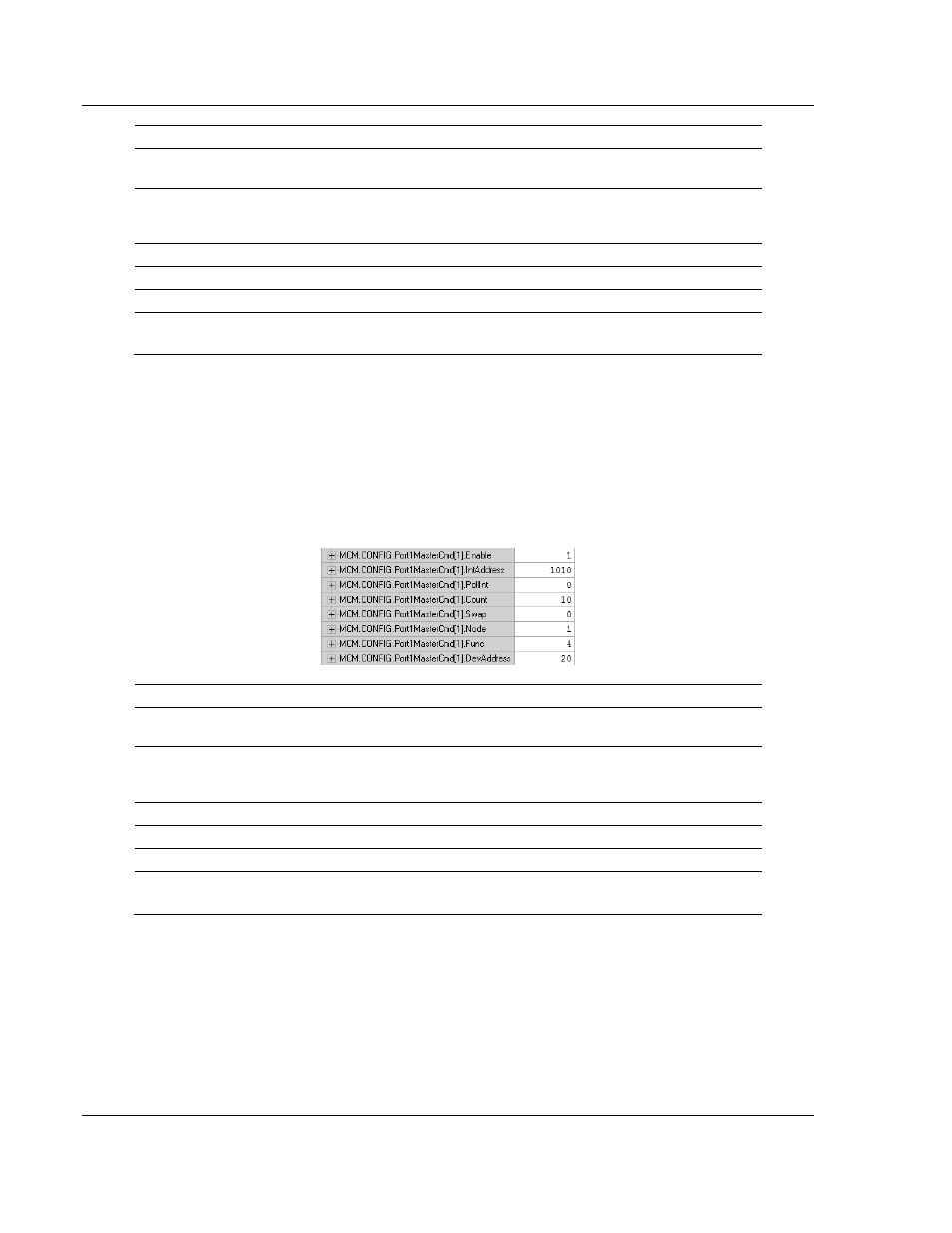
Below is a sample command to read Modbus addresses 30021 to 30030 of node
1 on the Modbus network.
Label
Description
Enable = 1
The module will send the command every time it goes through the
command list.
IntAddress = 1010
Places the data read from the Slave device into the module at address
1010. IntAddress 1010 of the module memory will be copied into the tag
MCM.DATA.R
EAD
D
ATA
[10].
Count = 10
Reads 10 consecutive registers from the Slave device.
Node = 1
Issues the Modbus command to node 1 on the network.
Func = 4
Issues Modbus Function Code 4 to Read Input Registers.
DevAddress =20
Function Code 4 DevAddress of 20 will read address 30021
Along with a count of 10, this command reads 30021 to 30030.
2.3.3 Read Coil Status 0x (Modbus Function Code 1)
Modbus Function Code 1 reads the Coils addressed at 0001 to 9999 from a
Slave device. These are bit values that are read using Modbus Function Code 1,
and can be written to using Function Code 5 or 15. Within a Slave device, this is
an individual bit value. Thus, the IntAddress field must be defined down to the bit
level within your MasterCmd.