Physical layer interface signals, Transceiver reconfiguration – Altera Stratix V Avalon-ST User Manual
Page 118
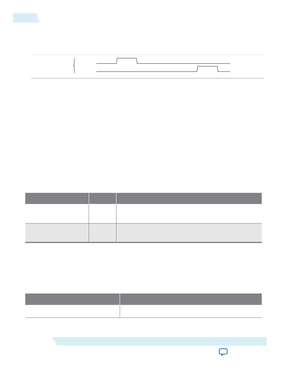
Figure 5-43: pme_to_sr and pme_to_cr in an Endpoint IP core
The following figure illustrates the behavior of
pme_to_sr
and
pme_to_cr
in an Endpoint. First, the Hard
IP receives the
PME_turn_off
message which causes
pme_to_sr
to assert. Then, the Application Layer
sends the
PME_to_ack
message to the Root Port by asserting
pme_to_cr
.
pme_to_sr
pme_to_cr
hard
IP
Physical Layer Interface Signals
Altera provides an integrated solution with the Transaction, Data Link and Physical Layers. The IP
Parameter Editor generates a SERDES variation file,
<variation>_serdes.v
or .vhd , in addition to the Hard
IP variation file,
<variation>.v
or
.vhd
. The SERDES entity is included in the library files for PCI Express.
Transceiver Reconfiguration
Dynamic reconfiguration compensates for variations due to process, voltage and temperature (PVT).
Among the analog settings that you can reconfigure are V
OD
, pre-emphasis, and equalization.
You can use the Altera Transceiver Reconfiguration Controller to dynamically reconfigure analog
settings. For more information about instantiating the Altera Transceiver Reconfiguration Controller IP
core refer to Hard IP Reconfiguration .
Table 5-23: Transceiver Control Signals
In this table, <n> is the number of interfaces required.
Signal Name
Direction
Description
reconfig_from_
xcvr[(<n>46)-1:0]
Output
Reconfiguration signals to the Transceiver Reconfiguration
Controller.
reconfig_to_xcvr[(<n>
70)-1:0]
Input
Reconfiguration signals from the Transceiver Reconfiguration
Controller.
The following table shows the number of logical reconfiguration and physical interfaces required for
various configurations. The Quartus II Fitter merges logical interfaces to minimize the number of physical
interfaces configured in the hardware. Typically, one logical interface is required for each channel and one
for each PLL. The ×8 variants require an extra channel for PCS clock routing and control. The ×8 variants
use channel 4 for clocking.
Table 5-24: Number of Logical and Physical Reconfiguration Interfaces
Variant
Logical Interfaces
Gen1 and Gen2 ×1
2
5-66
Physical Layer Interface Signals
UG-01097_avst
2014.12.15
Altera Corporation
Interfaces and Signal Descriptions