Altera Stratix V Avalon-ST User Manual
Page 62
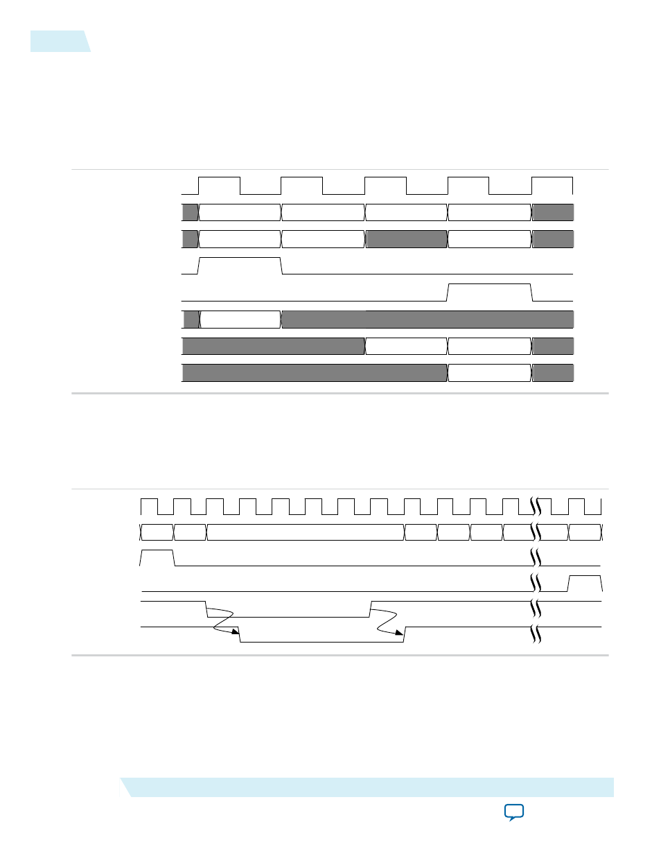
Figure 5-6: 64-Bit Avalon-ST rx_st_data<n> Cycle Definitions for 4-Dword Header TLPs with Non-
Qword Addresses
The following figure shows the mapping of Avalon-ST RX packet to PCI Express TLPs for TLPs for a four
dword header with non-qword addresses with a 64-bit bus. Note that the address of the first dword is 0x4.
The address of the first enabled byte is 0xC. This example shows one valid word in the first dword, as
indicated by the
rx_st_be
signal.
rx_st_be[7:4]
corresponds to
rx_st_data[63:32]
.
rx_st_be[3:0]
corresponds to
rx_st_data[31:0]
.
pld_clk
rx_st_data[63:32]
rx_st_data[31:0]
rx_st_sop
rx_st_eop
rx_st_bardec[7:0]
rx_st_be[7:4]
rx_st_be[3:0]
header1
header3
data0
data2
header0
header2
data1
10
C
F
F
Figure 5-7: 64-Bit Application Layer Backpressures Transaction Layer
The following figure illustrates the timing of the RX interface when the Application Layer backpressures
the Stratix V Hard IP for PCI Express by deasserting
rx
_st_ready
. The
rx_st_valid
signal deasserts
within three cycles after
rx_st_ready
is deasserted. In this example,
rx_st_valid
is deasserted in the
next cycle.
rx_st_data
is held until the Application Layer is able to accept it.
pld_clk
rx_st_data[63:0]
rx_st_sop
rx_st_eop
rx_st_ready
rx_st_valid
000 . 010 .
CCCC0002CCCC0001
CC
. CC
. CC
. CC
. CC
. CC
.
5-10
Data Alignment and Timing for the 64‑Bit Avalon‑ST RX Interface
UG-01097_avst
2014.12.15
Altera Corporation
Interfaces and Signal Descriptions