Interface – Altera Stratix V Avalon-ST User Manual
Page 84
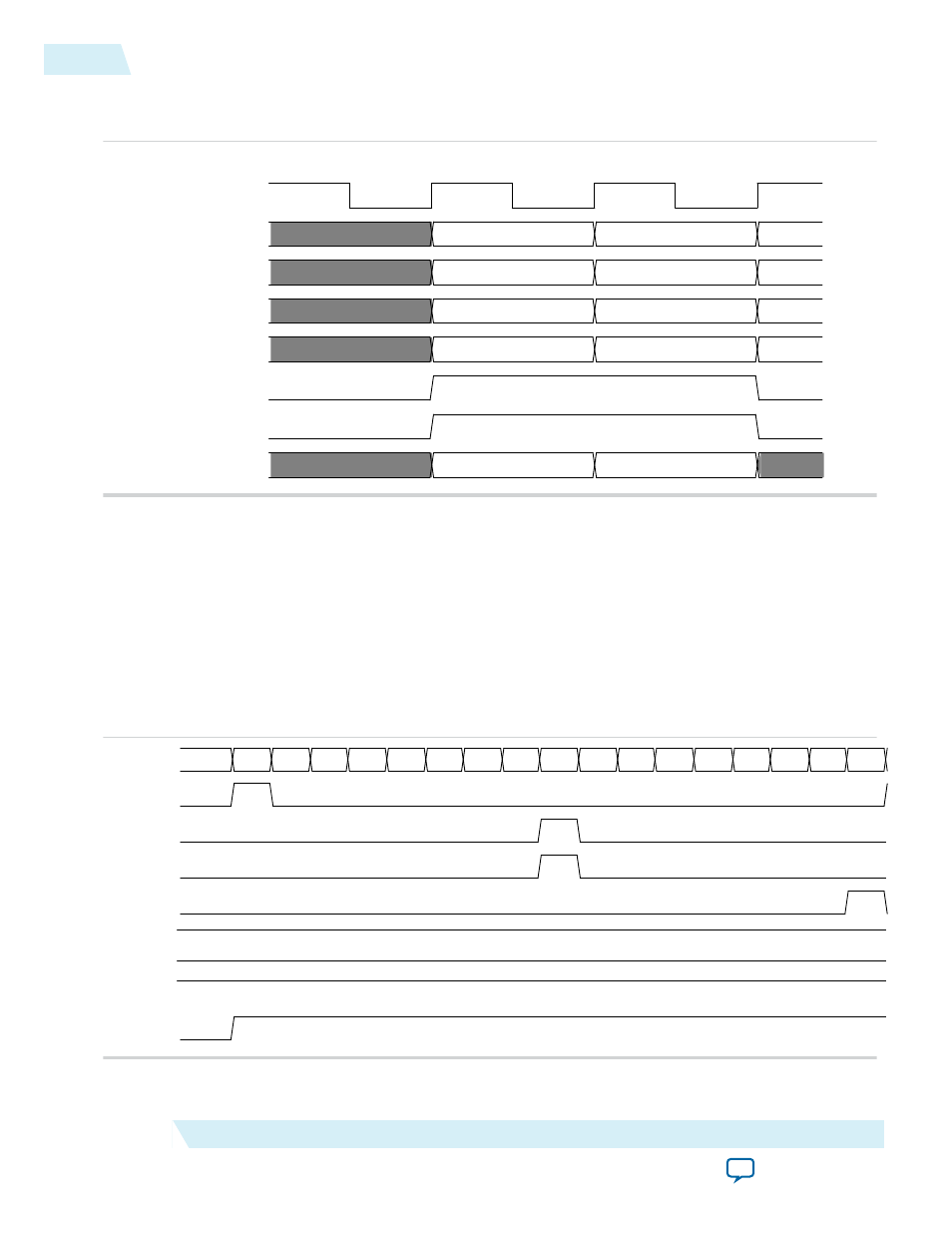
Figure 5-32: 256-Bit Avalon-ST tx_st_data Cycle Definition for 3-Dword Header TLP with Qword
Addresses
01
10
clk
tx_st_data[63:0]
Aligned Data
Unaligned Data
tx_st_data[127:64]
tx_st_data[191:128]
tx_st_data[255:192]
tx_st_sop
tx_st_eop
tx_st_empty[1:0]
Header 1 Header 0
XXXXXXXX Header 2
XXXXXXXX Data 0
XXXXXXXXX XXXXXXXX
Header 1 Header 0
Data 0 Header 2
XXXXXXXXX XXXXXXXX
XXXXXXXXX XXXXXXXX
Multiple Packets per Cycle on the Avalon-ST TX 256-Bit Interface
If you enable Multiple Packets Per Cycle under the Systems Settings heading, a TLP can start on a
128-bit boundary. This mode supports multiple start of packet and end of packet signals in a single cycle
when the Avalon-ST interface is 256 bits wide. The following figure illustrates this mode for a 256-bit
Avalon-ST TX interface. In this figure
tx_st_eop[0]
and
tx_st_sop[1]
are asserted in the same cycle.
Using this mode increases the complexity of the Application Layer logic but results in higher throughput,
depending on the TX traffic. Refer to Tradeoffs to Consider when Enabling Multiple Packets per Cycle for
an example of the bandwidth when Multiple Packets Per Cycle is enabled and disabled.
Figure 5-33: 256-Bit Avalon-ST TX Interface with Multiple Packets Per Cycle
tx_st_sop[0]
tx_st_eop[0]
tx_st_sop[1]
tx_st_eop[1]
tx_st_ready
tx_st_valid
tx_st_data[255:0]
12 ... 12...
12... 12...
12...
12... 12...
12... 00...
5A... 5A... 5A... 5A... 5A... 5A... 5A... 5A...
tx_st_empty[1:0]
5-32
Multiple Packets per Cycle on the Avalon-ST TX 256-Bit Interface
UG-01097_avst
2014.12.15
Altera Corporation
Interfaces and Signal Descriptions