Clocks, Clock domains – Altera Stratix V Avalon-ST User Manual
Page 149
For descriptions of the available reset signals, refer to Reset Signals, Status, and Link Training Signals.
Related Information
Reset, Status, and Link Training Signals
Clocks
The Hard IP contains a clock domain crossing (CDC) synchronizer at the interface between the
PHY/MAC and the DLL layers. The synchronizer allows the Data Link and Transaction Layers to run at
frequencies independent of the PHY/MAC. The CDC synchronizer provides more flexibility for the user
clock interface. Depending on parameters you specify, the core selects the appropriate
coreclkout_hip
.
You can use these parameters to enhance performance by running at a higher frequency for latency
optimization or at a lower frequency to save power.
In accordance with the PCI Express Base Specification, you must provide a 100 MHz reference clock that is
connected directly to the transceiver.
As a convenience, you may also use a 125 MHz input reference clock as input to the TX PLL.
Related Information
Clock Domains
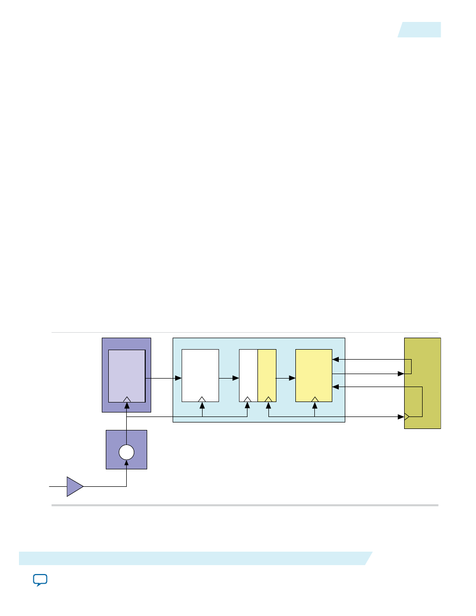
Figure 7-5: Clock Domains and Clock Generation for the Application Layer
The following illustrates the clock domains when using
coreclkout_hip
to drive the Application Layer
and the
pld_clk
of the IP core. The Altera-provided example design connects
coreclkout_hip
to the
pld_clk
. However, this connection is not mandatory.
100 MHz
(or 125 MHz)
refclk
Hard IP for PCI Express
PHY/MAC
Clock
Domain
Crossing
(CDC)
Data Link
and
Transaction
Layers
TX PLL
PCS
250 or 500 MHz
pclk
coreclkout_hip
Application
Layer
pld_clk
(62.5, 125
or 250 MHz)
serdes_pll_locked
pld_core_ready
Transceiver
UG-01097_avst
2014.12.15
Clocks
7-5
Reset and Clocks
Altera Corporation