Altera Stratix V Avalon-ST User Manual
Page 88
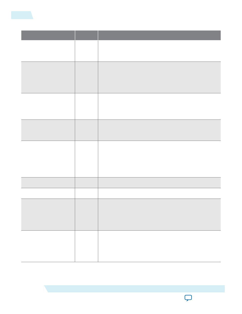
Table 5-7: Status and Link Training Signals
Signal
Direction
Description
serdes_pll_locked
Output
When asserted, indicates that the PLL that generates the
coreclkout_hip
clock signal is locked. In pipe simulation mode
this signal is always asserted.
pld_core_ready
Input
When asserted, indicates that the Application Layer is ready for
operation and is providing a stable clock to the
pld_clk
input. If
the
coreclkout_hip
Hard IP output clock is sourcing the
pld_
clk
Hard IP input, this input can be connected to the
serdes_
pll_locked
output.
pld_clk_inuse
Output
When asserted, indicates that the Hard IP Transaction Layer is
using the
pld_clk
as its clock and is ready for operation with the
Application Layer. For reliable operation, hold the Application
Layer in reset until
pld_clk_inuse
is asserted.
dlup
Output
When asserted, indicates that the Hard IP block is in the Data
Link Control and Management State Machine (DLCMSM) DL_
Up state.
dlup_exit
Output
This signal is asserted low for one
pld_clk
cycle when the IP
core exits the DLCMSM DL_Up state, indicating that the Data
Link Layer has lost communication with the other end of the
PCIe link and left the Up state. When this pulse is asserted, the
Application Layer should generate an internal reset signal that is
asserted for at least 32 cycles.
ev128ns
Output
Asserted every 128 ns to create a time base aligned activity.
ev1us
Output
Asserted every 1µs to create a time base aligned activity.
hotrst_exit
Output
Hot reset exit. This signal is asserted for 1 clock cycle when the
LTSSM exits the hot reset state. This signal should cause the
Application Layer to be reset. This signal is active low. When this
pulse is asserted, the Application Layer should generate an
internal reset signal that is asserted for at least 32 cycles.
l2_exit
Output
L2 exit. This signal is active low and otherwise remains high. It is
asserted for one cycle (changing value from 1 to 0 and back to 1)
after the LTSSM transitions from l2.idle to detect. When this
pulse is asserted, the Application Layer should generate an
internal reset signal that is asserted for at least 32 cycles.
5-36
Reset, Status, and Link Training Signals
UG-01097_avst
2014.12.15
Altera Corporation
Interfaces and Signal Descriptions