Logging neighbor state changes, Ospf frr configuration example – H3C Technologies H3C S12500-X Series Switches User Manual
Page 133
119
SubProtID: 0x1 Age: 04h20m37s
Cost: 4 Preference: 10
Tag: 0 State: Active Adv
OrigTblID: 0x0 OrigVrf: default-vrf
TableID: 0x2 OrigAs: 0
NBRID: 0x26000002 LastAs: 0
AttrID: 0xffffffff Neighbor: 0.0.0.0
Flags: 0x1008c OrigNextHop: 10.1.1.100
Label: NULL RealNextHop: 10.1.1.100
BkLabel: NULL BkNextHop: N/A
Tunnel ID: Invalid Interface: Vlan-interface11
BkTunnel ID: Invalid BkInterface: N/A
The output shows that Switch A communicates with Switch B through VLAN-interface 11.
245B
OSPF FRR configuration example
523B
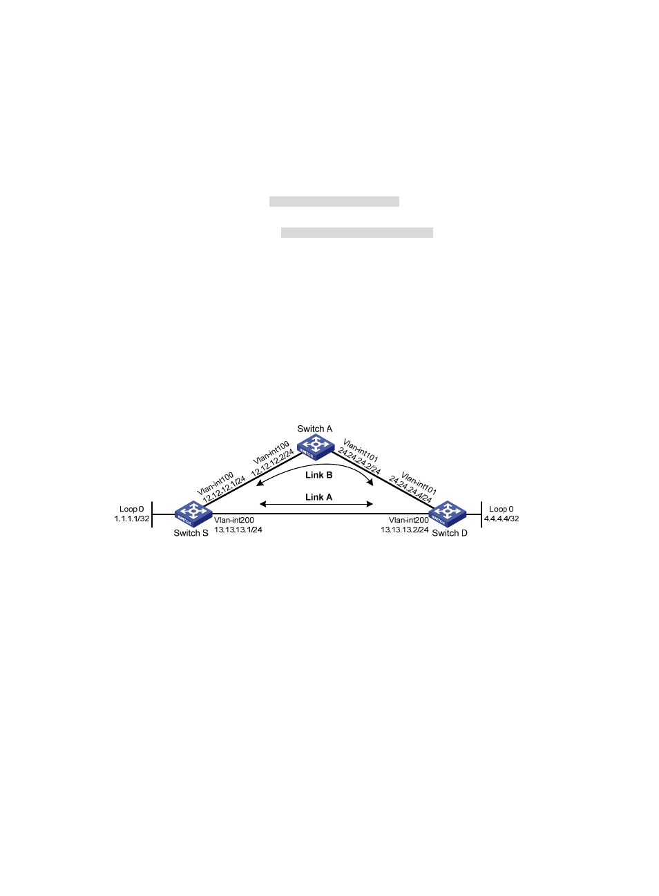
Network requirements
As shown in
1000H
Figure 31
, Switch S, Switch A, and Switch D reside in the same OSPF domain. Configure
OSPF FRR so that when the link between Switch S and Switch D fails, traffic is immediately switched to
Link B.
Figure 31 Network diagram
524B
Configuration procedure
1.
Configure IP addresses and subnet masks for interfaces on the switches. (Details not shown.)
2.
Configure OSPF on the switches to make sure Switch S, Switch A, and Switch D can communicate
with each other at the network layer. (Details not shown.)
3.
Configure OSPF FRR to automatically calculate the backup next hop:
You can enable OSPF FRR to either calculate a backup next hop by using the LFA algorithm, or
specify a backup next hop by using a routing policy.
{
(Method 1.) Enable OSPF FRR to calculate the backup next hop by using the LFA algorithm:
# Configure Switch S.
<SwitchS> system-view
[SwitchS] bfd echo-source-ip 1.1.1.1
[SwitchS] ospf 1
[SwitchS-ospf-1] fast-reroute lfa
[SwitchS-ospf-1] quit
# Configure Switch D.