Static route frr configuration example – H3C Technologies H3C S12500-X Series Switches User Manual
Page 33
19
Summary Count : 1
Destination/Mask Proto Pre Cost NextHop Interface
120.1.1.0/24 Static 65 0 10.1.1.100 Vlan11
Static Routing table Status : <Inactive>
Summary Count : 0
The output shows that Switch A communicates with Switch B through VLAN-interface 11.
139B
Static route FRR configuration example
454B
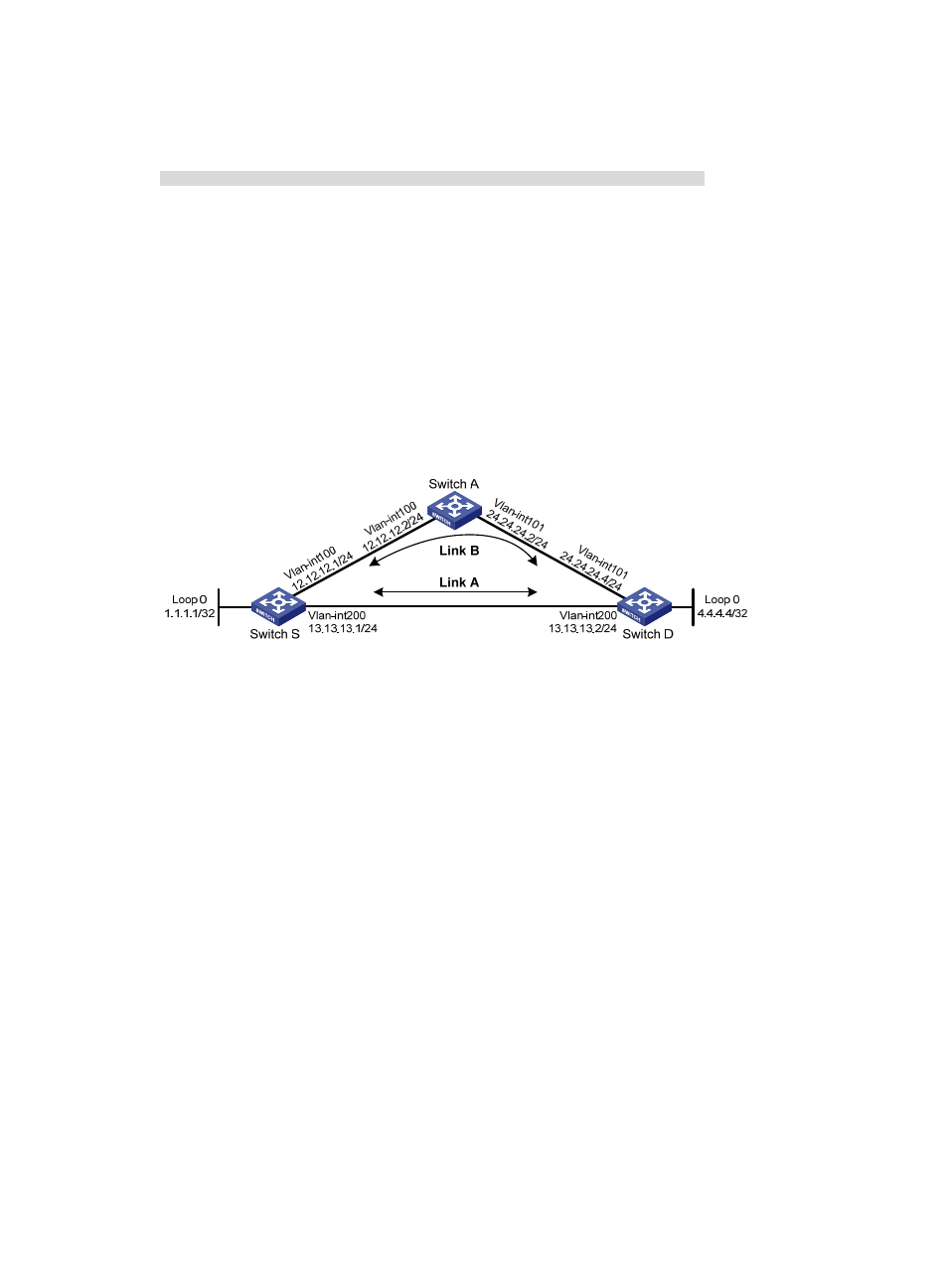
Network requirements
As shown in
898H
Figure 5
, configure static routes on Switch S, Switch A, and Switch D, and configure static
route FRR so when Link A becomes unidirectional, traffic can be switched to Link B immediately.
Figure 5 Network diagram
455B
Configuration procedure
1.
Configure IP addresses for interfaces. (Details not shown.)
2.
Configure static routes FRR on link A:
# Configure a static route on Switch S, and specify VLAN-interface 100 as the backup output
interface and 12.12.12.2 as the backup next hop.
<SwitchS> system-view
[SwitchS] bfd echo-source-ip 4.4.4.4
[SwitchS] ip route-static 4.4.4.4 32 vlan-interface 200 13.13.13.2 backup-interface
vlan-interface 100 backup-nexthop 12.12.12.2
# Configure a static route on Switch D, and specify VLAN-interface 101 as the backup output
interface and 24.24.24.2 as the backup next hop.
<SwitchD> system-view
[SwitchD] bfd echo-source-ip 1.1.1.1
[SwitchD] ip route-static 1.1.1.1 32 vlan-interface 200 13.13.13.1 backup-interface
vlan-interface 101 backup-nexthop 24.24.24.2
3.
Configure static routes on Switch A.
<SwitchA> system-view
[SwitchA] ip route-static 4.4.4.4 32 vlan-interface 101 24.24.24.4
[SwitchA] ip route-static 1.1.1.1 32 vlan-interface 100 12.12.12.1
456B
Verifying the configuration
# Display route 4.4.4.4/32 on Switch S to view the backup next hop information.