Bgp load balancing configuration example, Ospfv3 dr election configuration example – H3C Technologies H3C S12500-X Series Switches User Manual
Page 352
338
Type : I Cost : 1
NextHop : directly-connected Interface: Vlan400
Total: 2
Intra area: 1 Inter area: 1 ASE: 0
The output shows that route entries are reduced. All indirect routes are removed, except the default
route.
414B
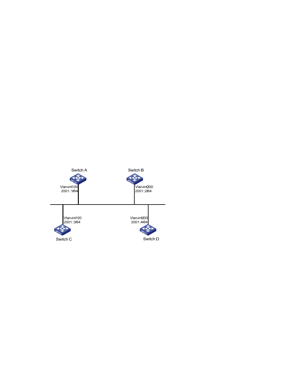
OSPFv3 DR election configuration example
670B
Network requirements
•
Configure router priority 100 for Switch A, the highest priority on the network, so it will become the
DR.
•
Configure router priority 2 for Switch C, the second highest priority on the network, so it will
become the BDR.
•
Configure router priority 0 for Switch B, so it cannot become a DR or BDR.
•
Switch D uses the default router priority 1.
Figure 80 Network diagram
671B
Configuration procedure
1.
Configure IPv6 addresses for interfaces. (Details not shown.)
2.
Configure basic OSPFv3:
# Configure Switch A: enable OSPFv3 and specify the router ID as 1.1.1.1.
<SwitchA> system-view
[SwitchA] ospfv3
[SwitchA-ospfv3-1] router-id 1.1.1.1
[SwitchA-ospfv3-1] quit
[SwitchA] interface vlan-interface 100
[SwitchA-Vlan-interface100] ospfv3 1 area 0
[SwitchA-Vlan-interface100] quit
# Configure Switch B: enable OSPFv3 and specify the router ID as 2.2.2.2.
<SwitchB> system-view
[SwitchB] ospfv3
[SwitchB-ospfv3-1] router-id 2.2.2.2