Rip configuration examples, Configuring basic rip – H3C Technologies H3C S12500-X Series Switches User Manual
Page 53
39
41B
RIP configuration examples
169B
Configuring basic RIP
466B
Network requirements
As shown in
929H
Figure 7
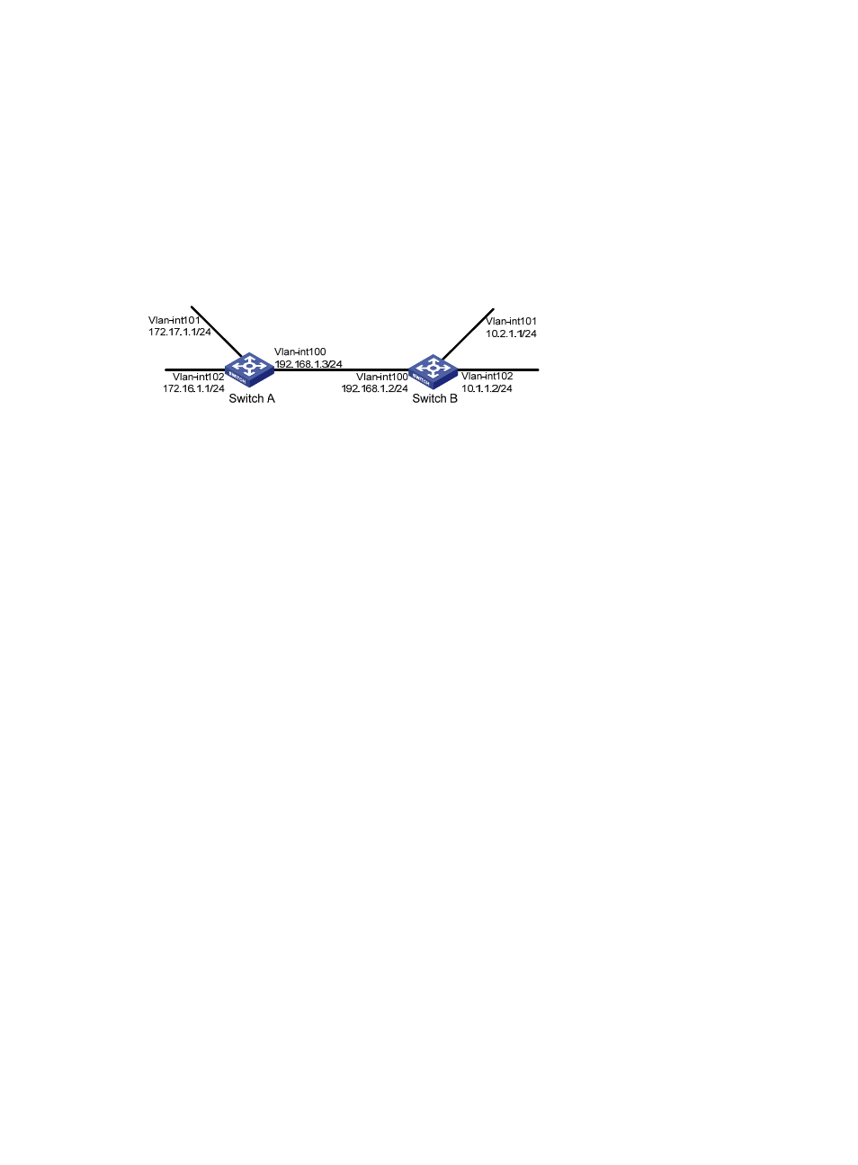
, enable RIPv2 on all interfaces on Switch A and Switch B. Configure Switch B to not
advertise route 10.2.1.0/24 to Switch A, and to accept only route 2.1.1.0/24 from Switch A.
Figure 7 Network diagram
467B
Configuration procedure
1.
Configure IP addresses for interfaces. (Details not shown.)
2.
Configure basic RIP by using either of the following methods:
(Method 1) # Enable RIP on the specified networks on Switch A.
<SwitchA> system-view
[SwitchA] rip
[SwitchA-rip-1] network 192.168.1.0
[SwitchA-rip-1] network 172.16.0.0
[SwitchA-rip-1] network 172.17.0.0
[SwitchA-rip-1] quit
(Method 2) # Enable RIP on the specified interfaces on Switch B.
<SwitchB> system-view
[SwitchB] rip
[SwitchB-rip-1] quit
[SwitchB] interface vlan-interface 100
[SwitchB-Vlan-interface100] rip 1 enable
[SwitchB-Vlan-interface100] quit
[SwitchB] interface vlan-interface 101
[SwitchB-Vlan-interface101] rip 1 enable
[SwitchB-Vlan-interface101] quit
[SwitchB] interface vlan-interface 102
[SwitchB-Vlan-interface102] rip 1 enable
[SwitchB-Vlan-interface102] quit
# Display the RIP routing table of Switch A.
[SwitchA] display rip 1 route
Route Flags: R - RIP
A - Aging, S - Suppressed, G - Garbage-collect
O - Optimal, F - Flush to RIB
----------------------------------------------------------------------------
Peer 192.168.1.2 on Vlan-interface100