Ospfv3 configuration examples, Ospfv3 area configuration example – H3C Technologies H3C S12500-X Series Switches User Manual
Page 348
334
Purpose Command
Display OSPFv3 statistics.
display ospfv3 [ process-id ] statistics [ error ]
Display OSPFv3 virtual link
information.
display ospfv3 [ process-id ] vlink
113B
OSPFv3 configuration examples
413B
OSPFv3 area configuration example
668B
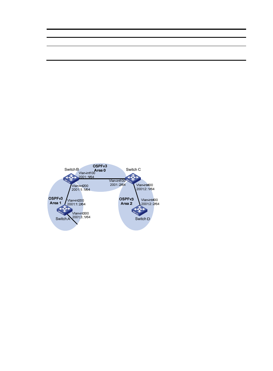
Network requirements
As shown in
1231H
Figure 79
:
•
Enable OSPFv3 on all switches.
•
Split the AS into three areas.
•
Configure Switch B and Switch C as ABRs to forward routing information between areas.
•
Configure Area 2 as a stub area to reduce LSAs in the area without affecting route reachability.
Figure 79 Network diagram
669B
Configuration procedure
1.
Configure IPv6 addresses for interfaces. (Details not shown.)
2.
Configure basic OSPFv3:
# Configure Switch A: enable OSPFv3 and specify the router ID as 1.1.1.1.
<SwitchA> system-view
[SwitchA] ospfv3
[SwitchA-ospfv3-1] router-id 1.1.1.1
[SwitchA-ospfv3-1] quit
[SwitchA] interface vlan-interface 300
[SwitchA-Vlan-interface300] ospfv3 1 area 1
[SwitchA-Vlan-interface300] quit
[SwitchA] interface vlan-interface 200
[SwitchA-Vlan-interface200] ospfv3 1 area 1
[SwitchA-Vlan-interface200] quit