Ospfv3 gr configuration example – H3C Technologies H3C S12500-X Series Switches User Manual
Page 358
344
Destination: 4::1/128 Protocol : Direct
NextHop : ::1 Preference: 0
Interface : InLoop0 Cost : 0
Destination: FE80::/10 Protocol : Direct
NextHop : :: Preference: 0
Interface : NULL0 Cost : 0
Destination: FF00::/8 Protocol : Direct
NextHop : :: Preference: 0
Interface : NULL0
416B
OSPFv3 GR configuration example
674B
Network requirements
•
As shown in
1233H
Figure 82
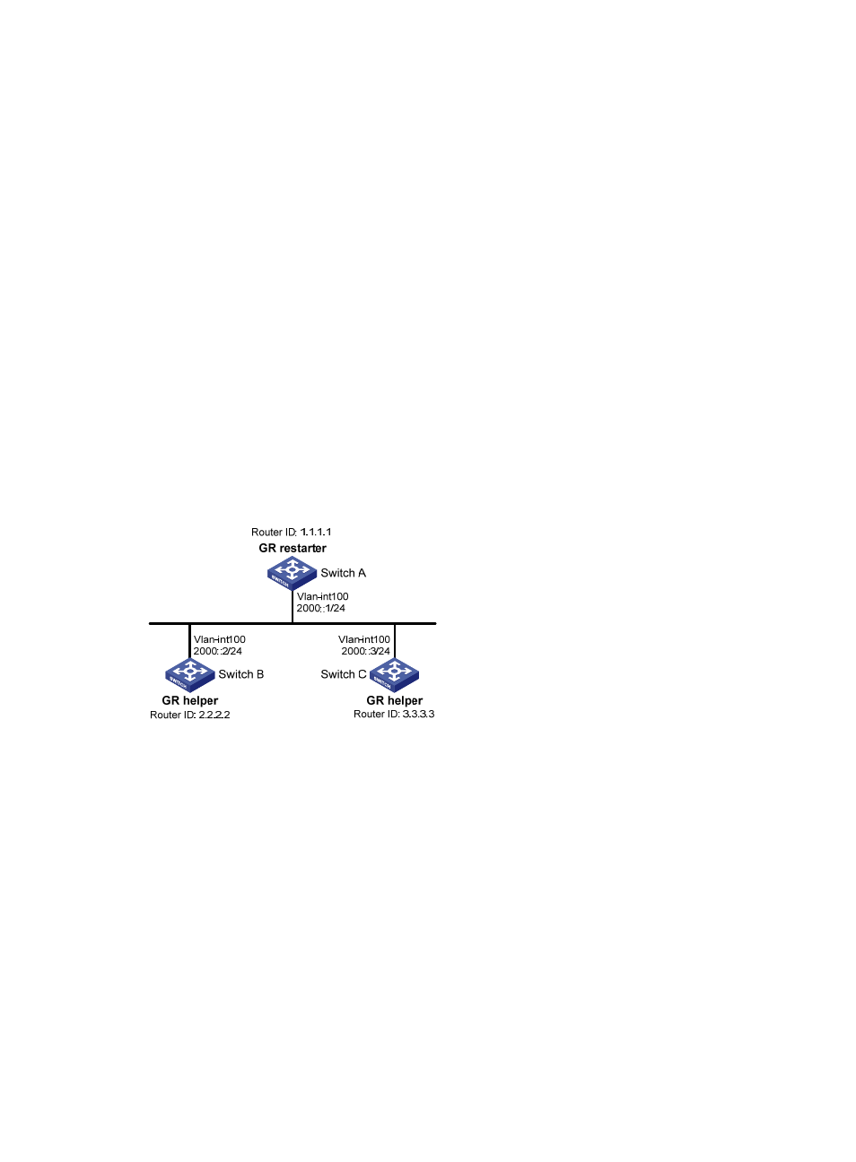
, Switch A, Switch B, and Switch C that reside in the same AS and the same
OSPFv3 routing domain are GR capable.
•
Switch A acts as the GR restarter. Switch B and Switch C act as the GR helpers, and synchronize
their LSDBs with Switch A through out-of-band (OOB) communication of GR.
Figure 82 Network diagram
675B
Configuration procedure
1.
Configure IPv6 addresses for interfaces. (Details not shown.)
2.
Configure basic OSPFv3:
# On Switch A, enable OSPFv3 process 1, enable GR, and set the router ID to 1.1.1.1.
<SwitchA> system-view
[SwitchA] ospfv3 1
[SwitchA-ospfv3-1] router-id 1.1.1.1
[SwitchA-ospfv3-1] graceful-restart enable
[SwitchA-ospfv3-1] quit
[SwitchA] interface vlan-interface 100
[SwitchA-Vlan-interface100] ospfv3 1 area 1
[SwitchA-Vlan-interface100] quit
# On Switch B, enable OSPFv3 and set the router ID to 2.2.2.2. (By default, GR helper is enabled
on Switch B.)
<SwitchB> system-view