Ietf ds-te configuration example, Network requirements – H3C Technologies H3C SR8800 User Manual
Page 140
129
LspIndex : 4098
Tunnel ID : 0x22002
LsrType : Ingress
Bypass In Use : Not Exists
BypassTunnel : Tunnel Index[---]
# Set the FRR polling timer to five seconds on PLR.
[RouterB] mpls
[RouterB-mpls] mpls te timer fast-reroute 5
[RouterB-mpls] quit
# Bring the protected outgoing interface up on PLR.
[RouterB] interface GigabitEthernet 3/1/2
[RouterB-GigabitEthernet3/1/2] undo shutdown
%Sep 7 09:01:31 2004 RouterB IFNET/5/UPDOWN:Line protocol on the interface
GigabitEthernet3/1/2 turns into UP state
# Perform the display interface tunnel command on Router A to identify the state of the primary LSP.
You can find that the tunnel interface is up.
# About 5 seconds later, perform the display mpls lsp verbose command on Router B. You can find
that Tunnel5 is still bound with interface GigabitEthernet 3/1/2 and is unused.
7.
Create a static route for routing MPLS TE tunnel traffic
[RouterA] ip route-static 4.1.1.2 24 tunnel 4 preference 1
Perform the display ip routing-table command on Router A. You can find a static route entry with
interface Tunnel4 as the outgoing interface.
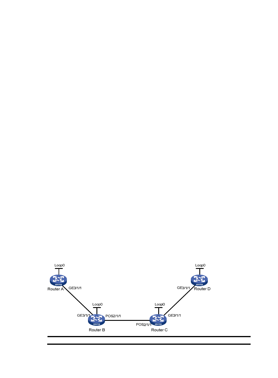
IETF DS-TE configuration example
Network requirements
Router A, Router B, Router C, and Router D are running IS-IS and all of them are Level-2 routers.
Use RSVP-TE to create a TE tunnel from Router A to Router D. Traffic of the tunnel belongs to CT 2, and the
tunnel needs a bandwidth of 4000 kbps.
For each link that the tunnel traverses, the maximum bandwidth is 10000 kbps, the maximum reservable
bandwidth is 10000 kbps, and BC 1, BC 2, and BC 3 are 8000 kbps, 5000 kbps, and 3000 kbps
respectively.
Figure 32 Network diagram
Device Interface IP
address
Device
Interface
IP address