Mpls ldp over mpls te – H3C Technologies H3C SR8800 User Manual
Page 65
54
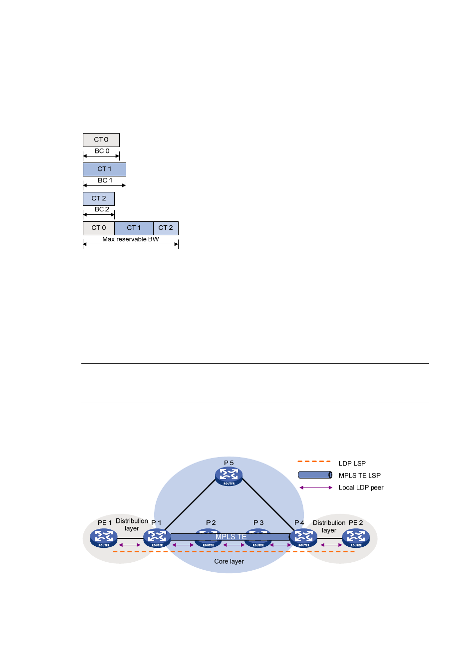
BC 0 is for CT 0. The bandwidth occupied by the traffic of CT 0 cannot exceed BC 0.
BC 1 is for CT 1. The bandwidth occupied by the traffic of CT 1 cannot exceed BC 1.
BC 2 is for CT 2. The bandwidth occupied by the traffic of CT 2 cannot exceed BC 2.
The total bandwidth occupied by CT 0, CT 1, and CT 2 cannot exceed the maximum reservable
bandwidth.
Figure 21 MAM bandwidth constraints model
3.
Check whether the traffic trunk matches an existing TE class.
The router checks whether the CT and the LSP setup/holding priority of the traffic trunk matches an
existing TE class. An MPLS TE tunnel can be established for the traffic trunk only when the following
conditions are satisfied:
Every node along the tunnel has a TE class that matches the traffic trunk’s CT and the LSP setup
priority.
Every node along the tunnel has a TE class that matches the traffic trunk’s CT and the LSP
holding priority.
NOTE:
The prestandard mode does not allow you to configure TE classes, while the IETF mode allows for TE class
configuration.
MPLS LDP over MPLS TE
Figure 22 Establish an LDP LSP across the network core layer