Deploying frr, Ps for an mpls te tunnel – H3C Technologies H3C SR8800 User Manual
Page 62
51
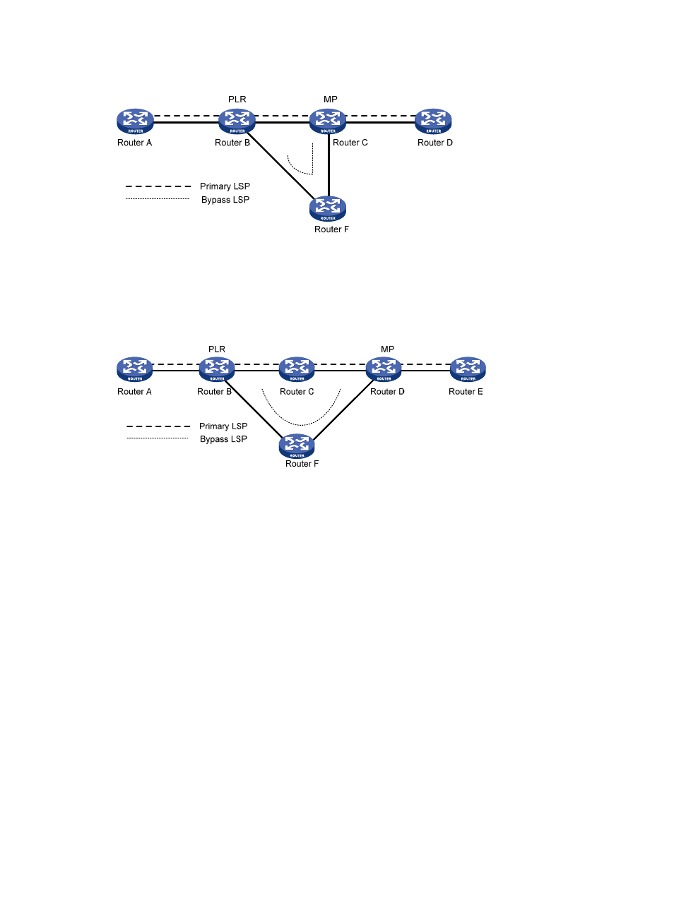
Figure 18 FRR link protection
•
Node protection, where the PLR and the MP are connected through a router and the primary LSP
traverses this router. When the router fails, traffic is switched to the bypass LSP. As shown in
, the primary LSP is Router A → Router B → Router C → Router D → Router E, and the bypass LSP
is Router B → Router F→ Router D. Router C is the protected router.
Figure 19 FRR node protection
Deploying FRR
When configuring the bypass LSP, make sure the protected link or node is not on the bypass LSP.
Because bypass LSPs are pre-established, FRR requires extra bandwidth. When network bandwidth is
insufficient, use FRR for crucial interfaces or links only.
PS for an MPLS TE tunnel
Protection switching (PS) refers to establishing one or more protection tunnels (backup tunnels) for a main
tunnel. A main tunnel and its protection tunnels form a protection group. When the main tunnel fails, data
is switched to a protection tunnel immediately, greatly improving the reliability of the network. When the
main tunnel recovers, data can be switched back to the main tunnel.
At present, the router supports only 1:1 protection switching, that is, one protection tunnel is used to
service one main tunnel. Between the ingress and egress, there are two tunnels, one main and one
backup. Normally, user data travels along the main tunnel. If the ingress finds a defect of the main tunnel
by using a probing mechanism, it will switch data to the protection tunnel.
Protection switching may be command triggered or signal triggered.
1.
Command switching refers to a PS triggered by an externally configured switching command,
which can define the following switching actions (in the descending order of priority):
clear—Clears all configured switching actions.
lock (lockout of protection)—Always uses the main LSP to transfer data.