Example for configuring svc mpls l2vpn, Network requirements, Configuration procedure – H3C Technologies H3C SR8800 User Manual
Page 220
209
Reply from 100.1.1.2: bytes=56 Sequence=2 ttl=255 time=60 ms
Reply from 100.1.1.2: bytes=56 Sequence=3 ttl=255 time=10 ms
Reply from 100.1.1.2: bytes=56 Sequence=4 ttl=255 time=70 ms
Reply from 100.1.1.2: bytes=56 Sequence=5 ttl=255 time=60 ms
--- 100.1.1.2 ping statistics ---
5 packet(s) transmitted
5 packet(s) received
0.00% packet loss
round-trip min/avg/max = 10/76/180 ms
Example for configuring SVC MPLS L2VPN
Network requirements
As shown in
, the CEs are connected to PEs through GigabitEthernet interfaces.
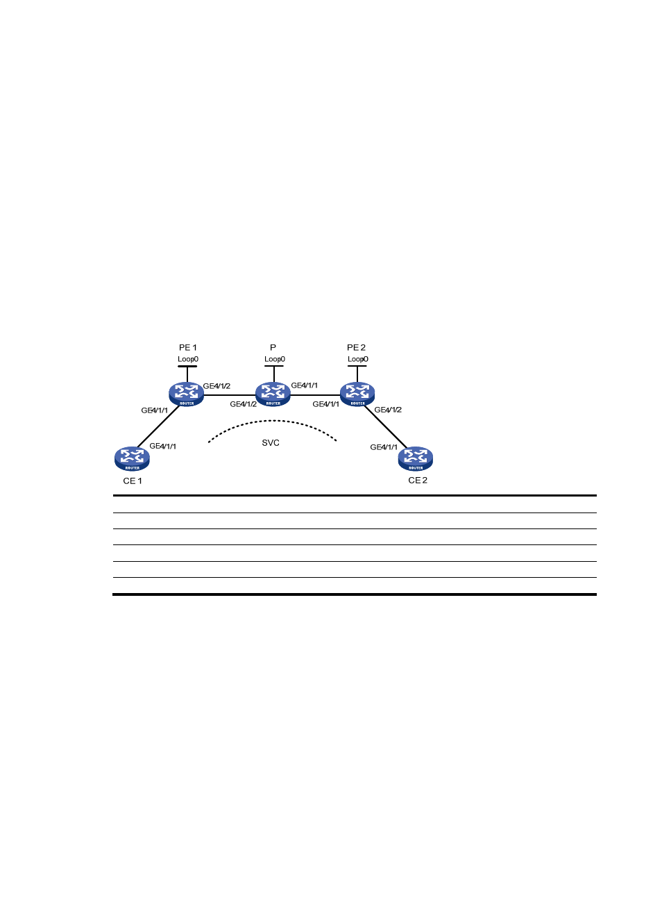
Establish an SVC MPLS L2VPN between CE 1 and CE 2.
Figure 51 Network diagram
Device Interface IP
address
Device
Interface
IP address
CE 1
GE4/1/1
100.1.1.1/24
P
Loop0
192.4.4.4/32
PE 1
Loop0
192.2.2.2/32
GE4/1/1
10.2.2.2/24
GE4/1/2
10.1.1.1/24
GE4/1/2 10.1.1.2/24
CE 2
GE4/1/1
100.1.1.2/24
PE 2
Loop0
192.3.3.3/32
GE4/1/1
10.2.2.1/24
Configuration procedure
The main steps are the following two:
•
Configure MPLS basic forwarding capability on the PEs and P router. This includes configuring the
LSR ID, enabling MPLS and LDP, and running IGP (OSPF in this example) between PE 1, the P router,
and PE 2 to establish LSPs.
•
Establish an SVC MPLS L2VPN connection. This includes enabling MPLS L2VPN on PE 1 and PE 2
and establishing an SVC connection and specifying the VC labels.
The detailed configuration procedure is as follows:
1.
Configure CE 1.
<Sysname> system-view
[Sysname] sysname CE1
[CE1] interface GigabitEthernet 4/1/1