Hub-spoke networking, Multi-hop pw – H3C Technologies H3C SR8800 User Manual
Page 171
160
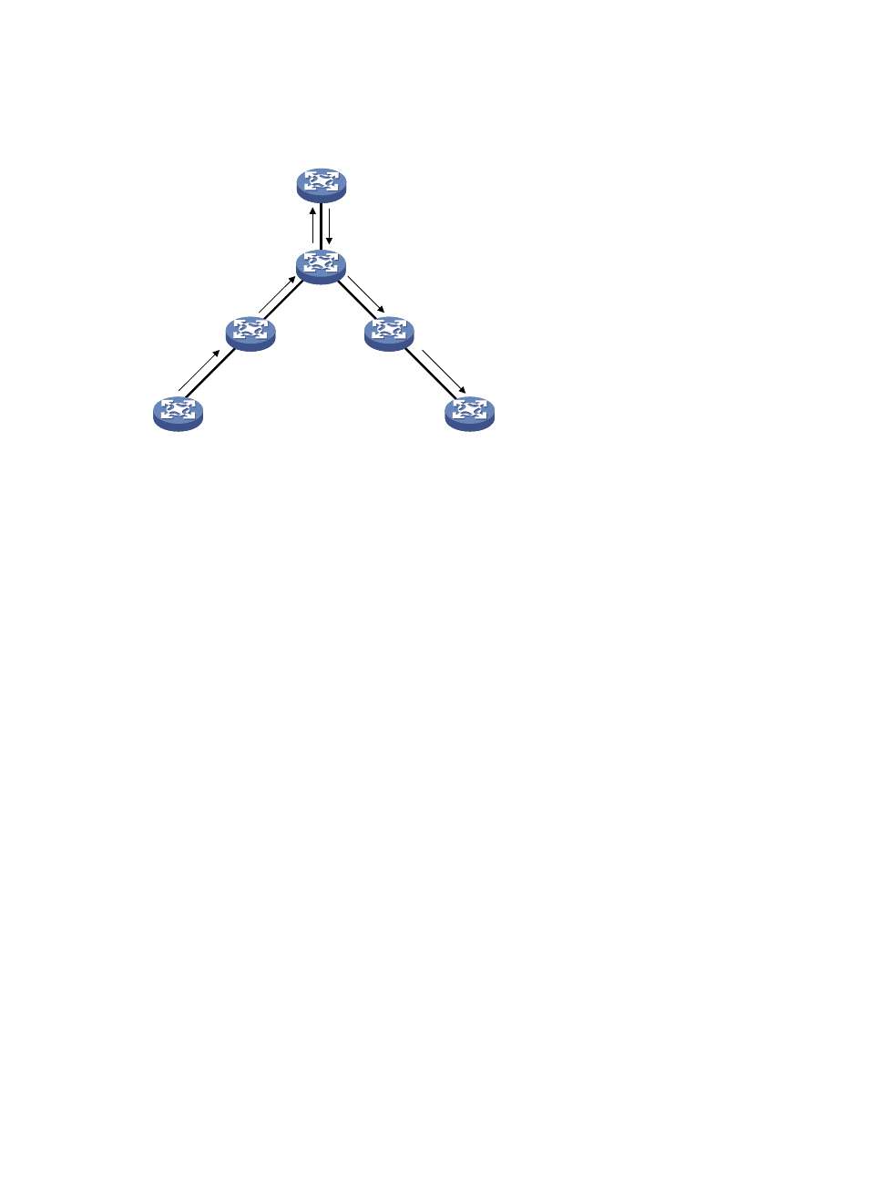
Hub-Spoke networking
Figure 40 Hub-spoke networking
shows a typical hub-spoke networking application. As the MAC address learning in a
hub-spoke network is the same as that in a common network, the following describes only the data
forwarding procedure:
1.
Upon receiving a packet from Spoke-CE 1, Spoke-PE 1 inserts an MPLS label into the packet
according to the VSI to which Spoke-CE 1 belongs and then forwards the packet to Hub-PE.
2.
Receiving the packet from the PW, Hub-PE determines by the MPLS label the VSI that the packet is
for and forwards the packet to Hub-CE directly.
3.
Hub-CE has Layer 2 forwarding function. It processes the packet and then forwards the packet
back to Hub-PE.
4.
Receiving the packet from the AC, Hub-PE determines by the VLAN tag the VSI that the packet is
for, inserts an MPLS label to which the PW corresponds based on the destination MAC address,
and forwards the packet to Spoke-PE 2.
5.
When Spoke-PE 2 receives the packet from the PW, it determines by the MPLS label the VSI that the
packet is for, and then forwards the packet to Spoke-CE 2.
Multi-hop PW
A PW cannot be setup directly between two PEs when:
•
The two PEs are in different Autonomous Systems (ASs), where they cannot establish a singling
connection.
•
The two PEs use different PW signaling protocols.
In such cases, you can establish multiple continuous PW segments that function as a single PW, called a
“multi-hop PW,” a virtual connection between the two PEs.
Hub-PE
Spoke-PE 1
Spoke-PE 2
Spoke-CE 1
Spoke-CE 2
Hub-CE