Working process – H3C Technologies H3C SR8800 User Manual
Page 64
53
NOTE:
•
The prestandard mode supports two CTs (CT 0 and CT 1), eight priorities, and up to 16 TE classes. The
IETF mode supports four CTs (CT 0 through CT 3), eight priorities, and up to eight TE classes.
•
The prestandard mode is proprietary, and therefore a device working in prestandard mode cannot
communicate with devices of some other vendors. The IETF mode is a standard mode implemented
according to relative RFCs. A device working in IETF mode can communicate with devices of other
vendors.
Working process
To establish MPLS TE tunnels according to CTs of traffic trunks, a router needs to:
1.
Determine the CT of traffic flows.
A router classifies traffic flows according to your configuration.
When configuring a dynamic MPLS TE tunnel, you can use the mpls te bandwidth command on
the tunnel interface to specify a CT for the traffic flows to be forwarded by the tunnel.
When configuring a static MPLS TE tunnel, you can use the bandwidth keyword to specify a CT
for the traffic flows to be forwarded along the tunnel.
2.
Check whether there is enough bandwidth available for the CT.
You can use the mpls te max-reservable-bandwidth command on an MPLS TE tunnel interface to
configure the bandwidth constraints of the tunnel interface. The router determines whether there is
enough bandwidth to establish an MPLS TE tunnel for a traffic trunk according to the traffic trunk’s
CT and the tunnel interface’s BCs.
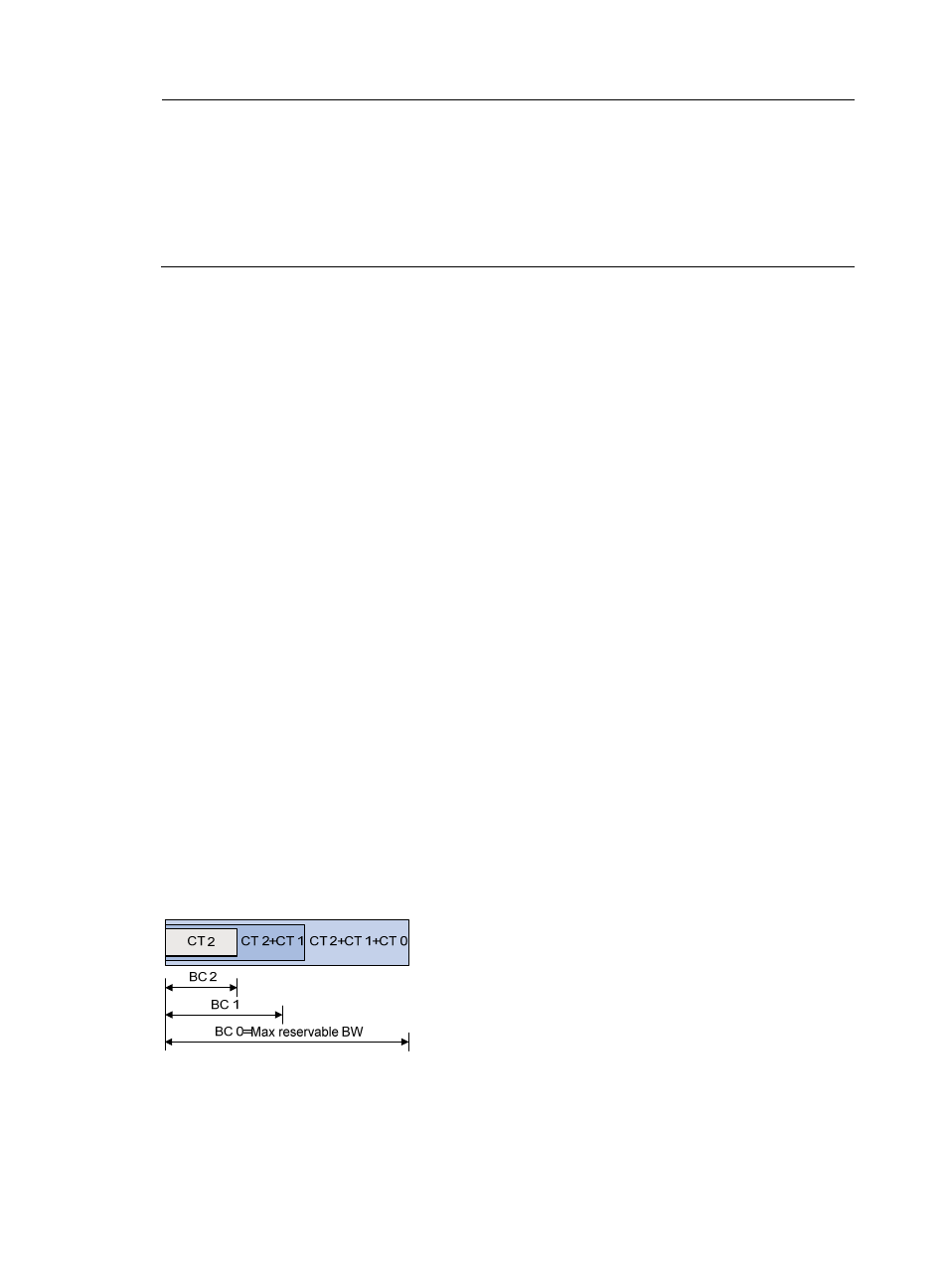
The relation between BCs and CTs varies in different BC models:
In RDM model, a BC constrains the total bandwidth of multiple CTs, as shown in
:
BC 2 is for CT 2. The total bandwidth of the traffic of CT 2 cannot exceed BC 2.
BC 1 is for CT 2 and CT 1. The total bandwidth of the traffic of CT 2 and CT 1 cannot exceed
BC 1.
BC 0 is for CT 2, CT 1, and CT 0. The total bandwidth of the traffic of CT 2, CT 1, and CT 0
cannot exceed BC 0. In this model, BC 0 equals the maximum reservable bandwidth of the
tunnel.
In cooperation with priority preemption, the RDM model can also implement the isolation across
CTs, ensuring each CT its share of bandwidth. RDM is suitable for networks where traffic is
unstable and traffic bursts may occur.
Figure 20 RDM bandwidth constraints model
In MAM model, a BC constrains the bandwidth of only one CT on an interface. This ensures
isolation across CTs no matter whether preemption is used or not. Compared with RDM, MAM is
easy to understand and configure. MAM is suitable for networks where traffic of each CT is
stable.