Fset 0x4 – Altera CPRI IP Core User Manual
Page 119
Chapter 7: Software Interface
7–3
CPRI Protocol Interface Registers
December 2013
Altera Corporation
CPRI MegaCore Function
User Guide
intr_hw_reset_en
[1]
RW
hw_reset interrupt enable. Controls whether a reset
request received over the CPRI link raises an interrupt on
the CPU IRQ line.
1’h0
intr_en
[0]
RW
CPRI protocol interface module interrupt enable.
The Ethernet and HDLC modules have separate interrupt
enable control bits.
1’h0
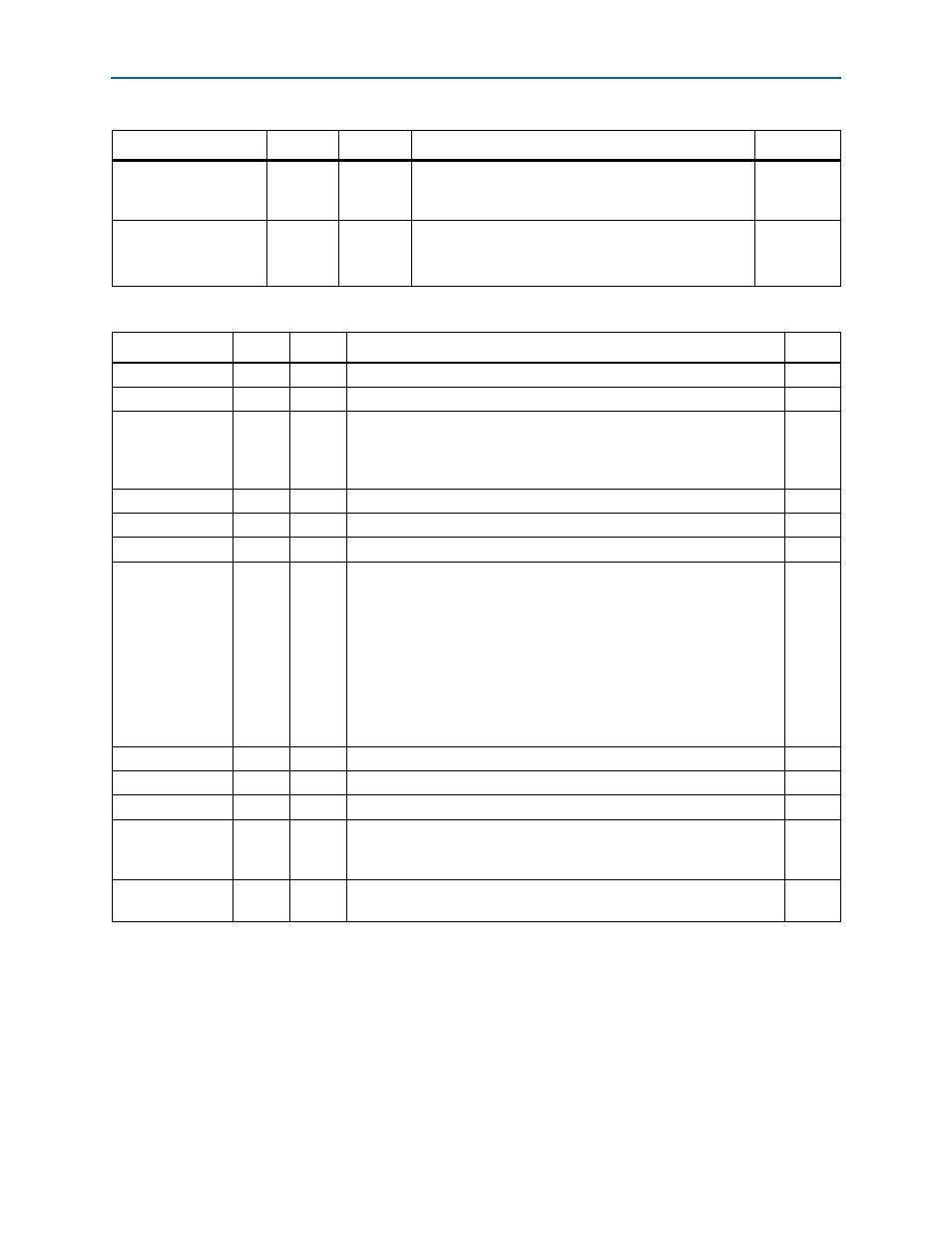
Table 7–4. CPRI_INTR—Interrupt Control and Status—Offset: 0x0 (Part 2 of 2)
Field Bits
Access
Function
Default
Table 7–5. CPRI_STATUS—CPRI Status—Offset: 0x4
Field Bits
Access
Function
Default
RSRV
[31:12] UR0
Reserved.
20'h0
rx_rfp_hold
[11]
RC
Radio frame pulse received. This bit is asserted every 10 ms.
1’h0
rx_freq_alarm_
hold
[10]
RC
CPRI receive clock is not synchronous with system clock
(
cpri_clkout
). This alarm is asserted each time mismatches are found
between the recovered CPRI receive clock and the system clock
cpri_clkout
.
1’h0
rx_state_hold
[9]
RC
Hold
rx_state
.
1’h0
rx_los_hold
[8]
RC
Hold
rx_los
.
1’h0
RSRV
[7:6]
UR0
Reserved.
2'h0
los_lcv
[5]
RO
Loss of signal (LOS) detected. This alarm is asserted if excessive line
code violations (LCVs) are detected, based on two counters and two
programmable threshold values. The first counter counts up to the
expected amount of time to CPRI link synchronization, during which the
second counter does not count LCVs. The second counter counts LCVs
up to the threshold—the number of LCVs after which this alarm is
asserted. The
CPRI_T_LCV
register at offset 0x54 specifies the expected
amount of time to CPRI link synchronization, and the
CPRI_N_LCV
register at offset 0x50 holds the threshold number of LCVs after which
this alarm is asserted.
1’h0
RSRV
[4]
UR0
Reserved.
1'h0
rx_bfn_state
[3]
RO
Indicates BFN (Node B radio frame) synchronization has been achieved.
1’h0
rx_hfn_state
[2]
RO
Indicates HFN synchronization has been achieved.
1’h0
rx_state
[1]
RO
When set, indicates that Rx HFN and BFN synchronization have been
achieved in CPRI receiver frame synchronization. You can read this field
to determine whether the Rx link is established.
1’h0
rx_los
[0]
RO
Indicates either excessive 8B/10B violations (> 15) or incoming LOS
signal on dedicated line from SFP optical module (
gxb_los
signal).
1’h0
Note to
(1) This register field is a read-to-clear field. You must read the register twice to read the true value of the field after frame synchronization is
achieved. If you observe this bit asserted during link initialization, read the register again after link initialization to confirm any errors.