Map transmitter in fifo mode, Map transmitter in fifo mode –26, Fifo mode – Altera CPRI IP Core User Manual
Page 58: Mode
4–26
Chapter 4: Functional Description
MAP Interface
CPRI MegaCore Function
December 2013
Altera Corporation
User Guide
For descriptions of the signals in
and to the
following sections.
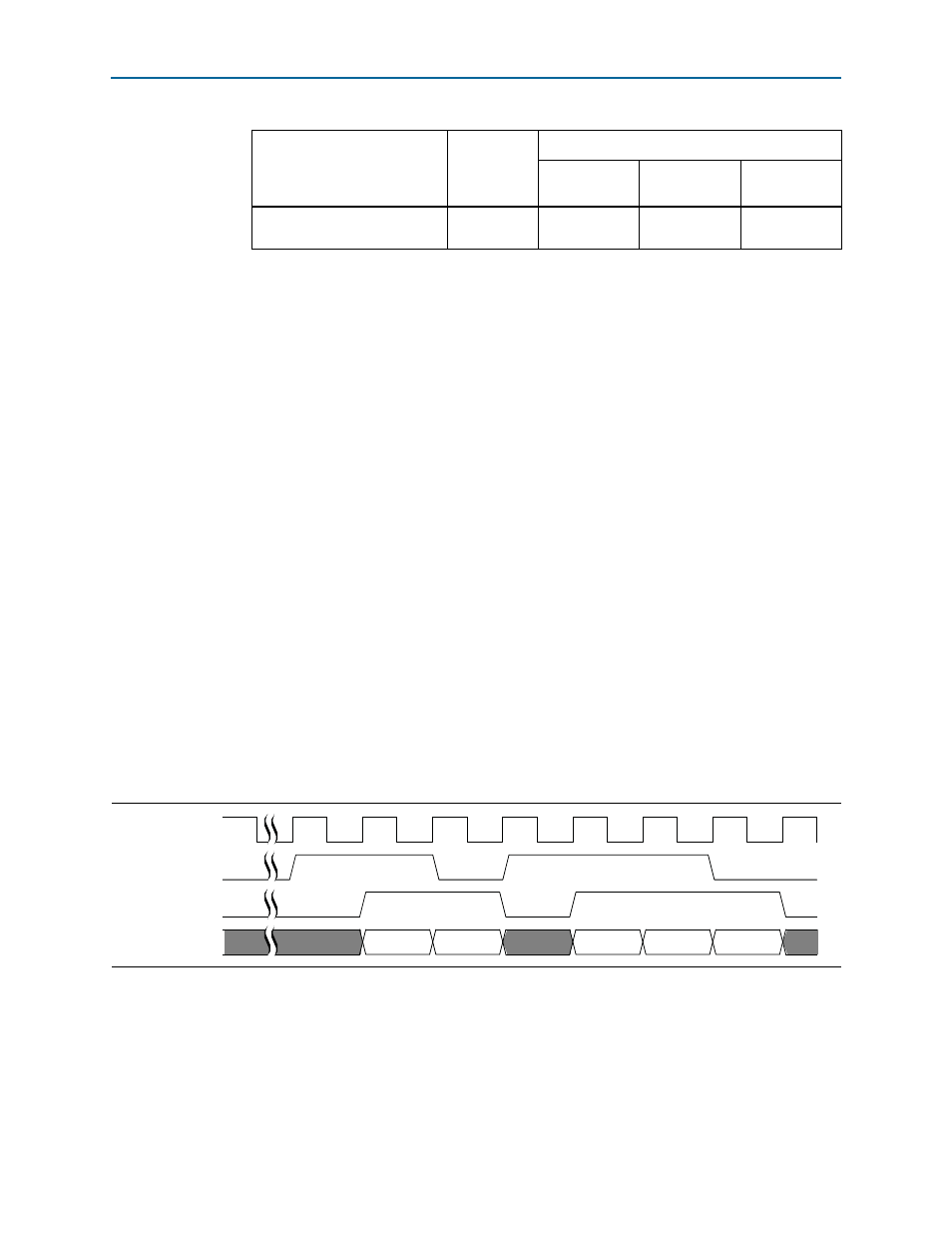
MAP Transmitter in FIFO Mode
In FIFO mode, each data channel, or AxC interface, has an output ready signal,
mapN_tx_ready
. Each AxC interface asserts its ready signal when it is ready to receive
data on this data channel for transmission to the CPRI protocol interface—when the
buffer level is at or below the threshold indicated in the
CPRI_MAP_TX_READY_THR
register.
After the CPRI IP core asserts the
mapN_tx_ready
signal, the application is expected to
respond by asserting the
mapN_tx_valid
signal and presenting data on
mapN_tx_data
.
In every
mapN_tx_clk
cycle immediately following a
mapN_tx_clk
cycle in which
mapN_tx_ready
is (becomes or remains) asserted, the application can present valid
data on
mapN_tx_data
, as prescribed by the Avalon-ST specification with
READY_LATENCY
value 1.
For details about the behavior of the individual signals in FIFO mode, refer to
Transmitter Signals” on page 6–3
shows the expected typical behavior of
the MAP Tx signals in this synchronization mode.
FIFO-based communication is simple but does not allow easy control of buffer delay.
The delay through each mapN Tx buffer depends on your programmed threshold
value and the application. Data is not read from the mapN Tx buffer until the buffer
threshold is reached, so the delay through the buffer depends on the fill level. Each
AxC interface has the same buffer threshold, but each Tx buffer reaches that threshold
independently.
map{23…0}_tx_status_data
[2:0]
Output
v
v
v
Notes to
(1) A checkmark indicates the signal is used in a synchronization mode, and a dash indicates the signal is not used in
that synchronization mode.
(2) An entry with a dash indicates a signal that does not participate in the MAP receiver interface communication in
this synchronization mode. The signal is either not present in the configuration or is ignored. An input signal that
is ignored is ignored by the CPRI IP core. An output signal that is ignored should be ignored by the application.
Refer to
for information about the case that is relevant for each signal.
Table 4–12. MAP Transmitter Interface Signals by Synchronization Mode
(1)
(Part 2 of 2)
Signal Name
Direction
Available in Synchronization Mode
FIFO
Synchronous
Buffer
Internally
Clocked
Figure 4–13. MAP Transmitter Interface in FIFO Mode
mapN_tx_clk
mapN_tx_ready
mapN_tx_valid
mapN_tx_data[31:0]