Altera CPRI IP Core User Manual
Page 47
Chapter 4: Functional Description
4–15
MAP Interface
December 2013
Altera Corporation
CPRI MegaCore Function
User Guide
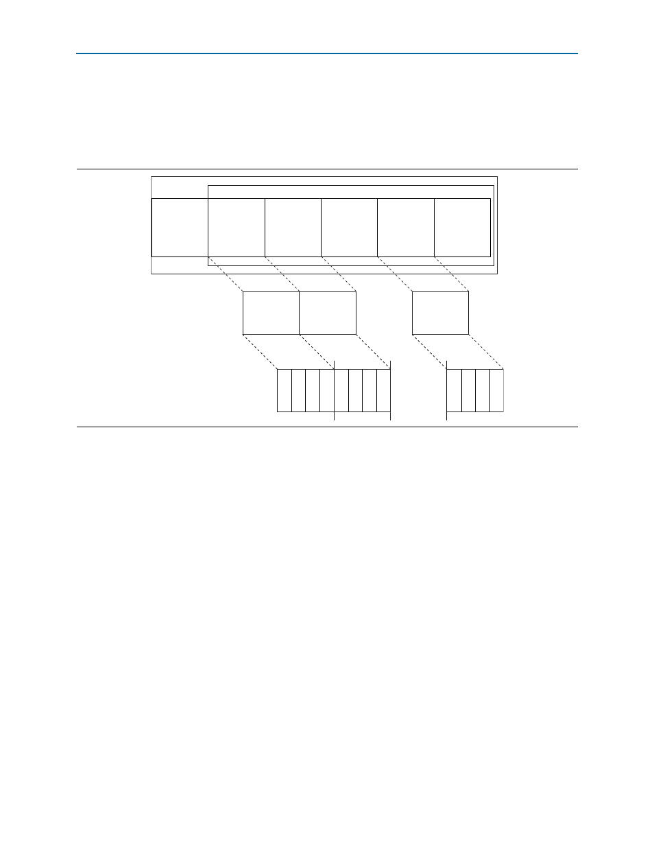
In the basic mapping mode, AxC containers are packed in the IQ data block in the
packed position (Option 1) illustrated in Section 4.2.7.2.3 of the CPRI V4.2
Specification.
shows how the AxC containers map to the individual active
data channels. The oversampling factor is the number of 32-bit data words in each
AxC container.
1
The CPRI IP core does not support AxC interface reordering. When the value of
map_ac
is less than N_MAP, the first
map_ac
AxC interfaces, of the existing N_MAP
interfaces, are active. Note that an active AxC interface transmits and receives data on
its data channel based on the values of the relevant
map_rx_enable
bit of the
CPRI_IQ_RX_BUF_CONTROL
register and the relevant
map_tx_enable
bit of the
CPRI_IQ_TX_BUF_CONTROL
register. Any data in an AxC container for an active but
disabled channel is ignored, and an incoming AxC container designated from a
disabled channel is ignored.
The
map_15bit_mode
field of the
CPRI_MAP_CONFIG
register specifies the sample width.
The sample width is the number of significant bits —15 or 16—in each 16-bit half
(originally, I- or Q-sample) of the 32-bit data word on the Avalon-ST data channel. In
15-bit mode, the least significant bit in each half of the 32-bit word is ignored when
received from the data channel on input signal
mapN_tx_data[31:0]
, and is set to 0
when transmitted on the data channel in output signal
mapN_rx_data[31:0]
.
Therefore, bit 15 and bit 31 of the data word correspond to bit 14 of the I and Q
samples, respectively; bit 1 and bit 17 of the data word correspond to bit 0 of the I and
Q samples, respectively; and bits 0 and 16 of the data word are ignored. In 16-bit
mode, bit 15 and bit 31 of the data word correspond to bit 15 of the I and Q samples,
respectively, and bit 0 and bit 16 of the data word correspond to bit 0 of the I and Q
samples, respectively.
shows the bit correspondence for both sample
widths.
Figure 4–7. CPRI Basic Mapping Mode
Control
Words
AxC
Container
1
AxC
Container
2
...
...
AxC
Container
map_ac
Reserved
Bits
IQ Data Block
Basic Frame
AxC
Interface
0
Data
AxC
Interface
1
Data
AxC
Interface
map_ac
Data
...
Data W
ord
1
Data W
ord
2
Data W
ord
map_n_ac
...
Data W
ord
1
Data W
ord
2
Data W
ord
map_n_ac
...
Data W
ord
1
Data W
ord
2
Data W
ord
map_n_ac
...