Map transmitter interface, Map transmitter interface –24, Figure 4–12 – Altera CPRI IP Core User Manual
Page 56
4–24
Chapter 4: Functional Description
MAP Interface
CPRI MegaCore Function
December 2013
Altera Corporation
User Guide
■
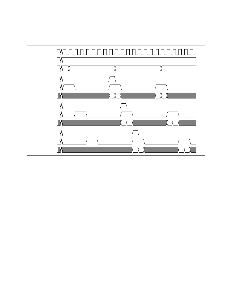
In the
CPRI_MAP_OFFSET_RX
register, the
cpri_rx_offset_z
field has the value of 3
and the
cpri_rx_offset_x
field has the value of 4.
In
, the
map0_rx_start
signal pulses synchronously with the first rising
edge of
map0_rx_valid
following the CPRI frame offset specified in the
CPRI_MAP_OFFSET_RX
register. The
mapN_rx_valid
signals are asserted in round-robin
order, following the basic mapping mode.
The internally-clocked mode is useful only with the basic mapping mode. The
advantage of the advanced mapping modes is their support for different clocks on
different antenna-carrier interfaces, a feature not available with the internally-clocked
synchronization mode.
MAP Transmitter Interface
The MAP transmitter interface receives data from the data channels and passes it to
the CPRI protocol interface to transmit on the CPRI link. The MAP transmitter
implements an Avalon-ST interface protocol. Refer to
for details of the interface communication signals.
Figure 4–12. MAP Receiver Interface in the internally-Clocked Mode
cpri_clkout
cpri_rx_hfn
cpri_rx_x
map0_rx_start
map0_rx_valid
map0_rx_data[31:0]
map1_rx_start
map1_rx_valid
map1_rx_data[31:0]
map2_rx_start
map2_rx_valid
map2_rx_data[31:0]
3
3
4
5
6