Extended rx delay measurement – Altera CPRI IP Core User Manual
Page 184
E–6
Appendix E: Delay Measurement and Calibration
Single-Hop Delay Measurement
CPRI MegaCore Function
December 2013
Altera Corporation
User Guide
Extended Rx Delay Measurement
The next component of the link delay is the delay through the CPRI Receive
buffer. The latency of the CPRI Receive buffer depends on the number of 32-bit
words currently stored in the buffer, and the phase difference between the
recovered receive clock, which is used to write data to the buffer, and the system
clock
cpri_clkout
, which is used to read data from the buffer. The CPRI IP core
uses a dedicated clock,
clk_ex_delay
, to measure the Rx buffer delay to your
desired precision. The
ex_delay
field of the
CPRI_EX_DELAY_CONFIG
register
contains the value N, such that N clock periods of the
clk_ex_delay
clock are
equal to some whole number M of
cpri_clkout
periods. For example, N may be a
multiple of M, or the M/N frequency ratio may be slightly greater than 1, such as
64/63 or 128/127. The application layer specifies N to ensure the accuracy your
application requires. The accuracy of the Rx buffer delay measurement is
N/least_common_multiple(N,M)
cpri_clkout
periods.
1
If your application does not require this precision, drive the
clk_ex_delay
input port with the
cpri_clkout
signal. In this case, the M/N ration is 1
because the frequencies are the same. Read the Rx buffer delay from the
CPRI_RX_DELAY
register at offset 0x34 and use it in the Rx delay calculation.
Alternatively, you can tie off the
clk_ex_delay
signal.
The
rx_buf_delay
field of the
CPRI_RX_DELAY
register indicates the number of
32-bit words currently in the Rx buffer. After you program the
ex_delay
field of
the
CPRI_EX_DELAY_CONFIG
register with the value of N, the
rx_ex_buf_delay
field
of the
CPRI_EX_DELAY_STATUS
register holds the current measured delay through
the Rx buffer. The unit of measurement is
cpri_clkout
periods. The
ex_buf_delay_valid
field indicates that a new measurement has been written to
the
rx_ex_buf_delay
field since the previous register read. The following sections
explain how you set and use these register values to derive the extended Rx delay
measurement information.
M/N Ratio Selection
As your selected M/N ratio approaches 1, the accuracy provided by the use
of the
clk_ex_delay
clock increases.
Table E–2
shows some example M/N
ratios and the resolutions they provide, for a CPRI IP core that runs at data
rate 3072 Mbps and targets a Stratix IV GX device.
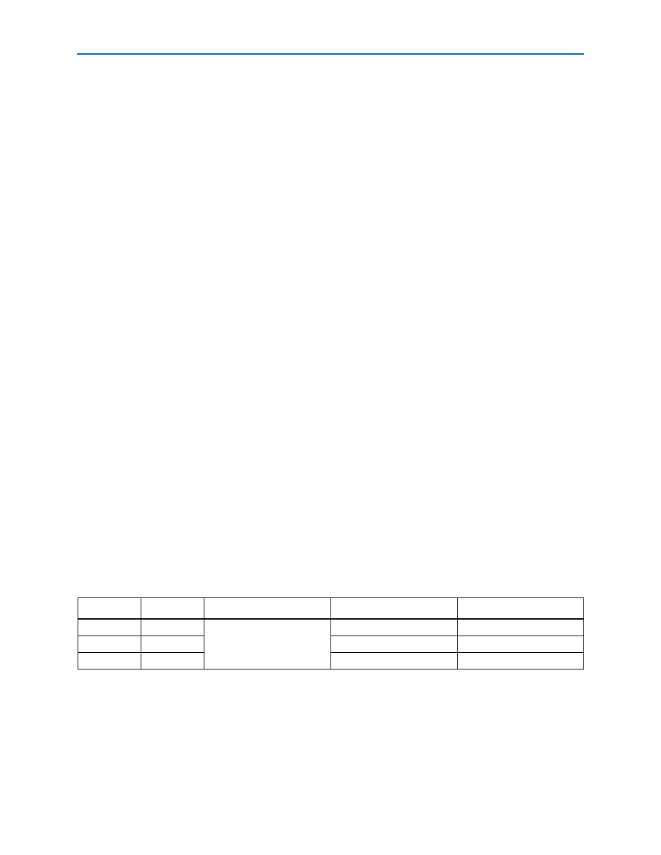
Table E–2. Resolution as a Function of M/N Ratio at 3072 Mbps on a Stratix IV GX Device
M
N
cpri_clkout Period
(1)
clk_ex_delay Period
(2)
Resolution
128
127
13.02 ns
(1/76.80 MHz)
13.12 ns
±100 ps
64
63
13.22 ns
±200 ps
1
4
3.25 ns
±3.25 ns
Notes to
Table E–2
:
(1)
cpri_clkout
frequency for each CPRI data rate and device family.
(2)
“Calculation Example: Rx Buffer Delay”
shows you how to calculate the
clk_ex_delay
clock period for a given M, N, and
cpri_clkout
period.