Altera CPRI IP Core User Manual
Page 180
E–2
Appendix E: Delay Measurement and Calibration
Delay Requirements
CPRI MegaCore Function
December 2013
Altera Corporation
User Guide
Requirement R-19 specifies that the link delay accuracy for the downlink between the
synchronization master SAP and the synchronization slave SAP, excluding the cable
length, be within ±8.138 ns. Requirements R-20 and R-21 extrapolate this requirement
to single-hop round-trip delay accuracy. R-20 requires that the accuracy of the
round-trip delay, excluding cables, be within ±16.276 ns, and R-21 requires that the
round-trip cable delay measurement accuracy be within the same range. Requirement
R-21A extrapolates this requirement further, to multihop round-trip delay accuracy. In
calculating these delays, Altera assumes that the downlink and uplink cable delays
have the same duration.
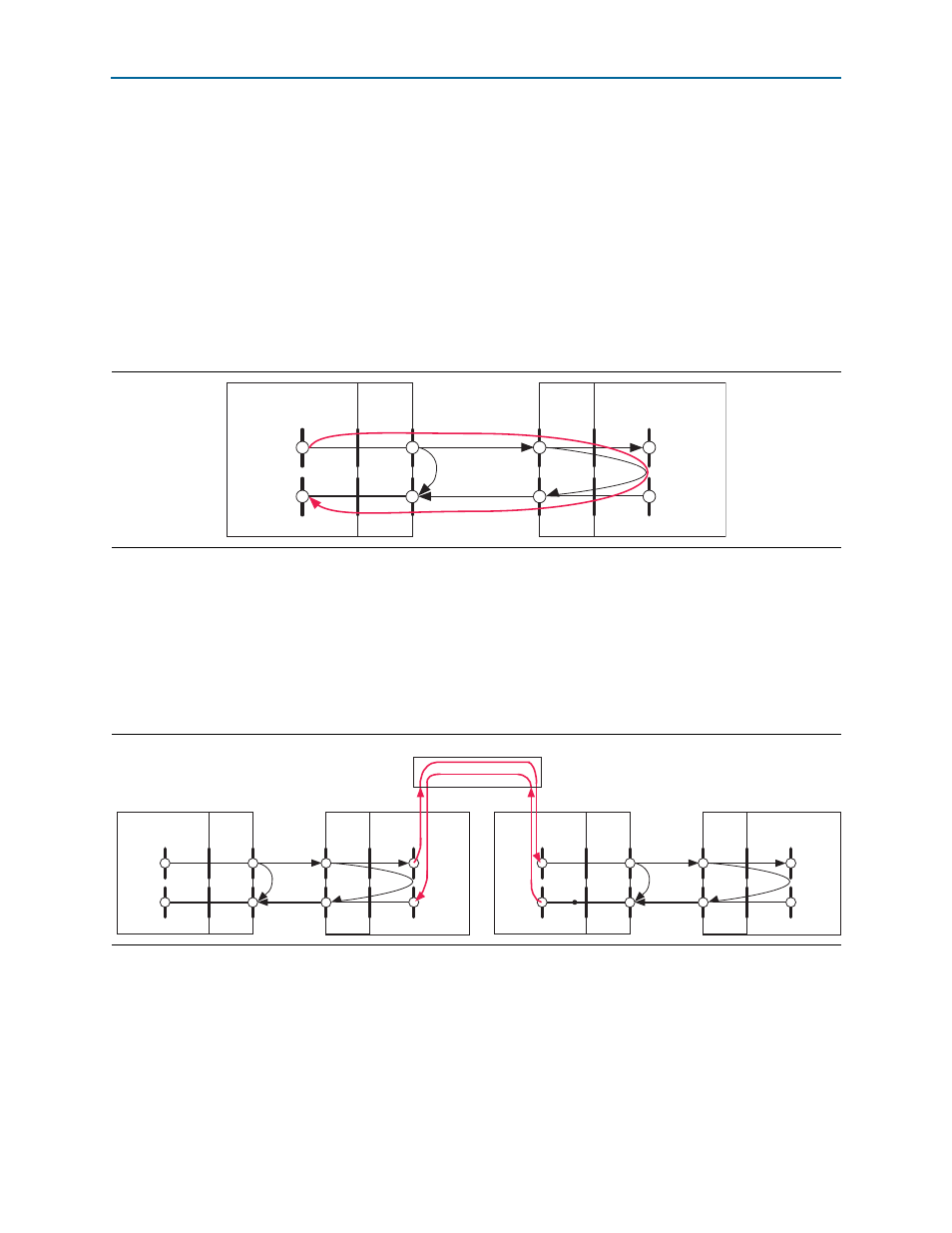
Figure E–1
shows the reference points you can use to determine the CPRI IP core
delay measurements for single-hop CPRI configurations.
CPRI requirement R-21 addresses the accuracy of the round-trip cable delay, which is
the sum of the T12 and T34 delays. The T12 and T34 delays are assumed to have the
same duration.
Figure E–2
shows the reference points you can use to determine the CPRI IP core
delay measurements for multihop CPRI configurations. The duration of TBdelay
depends on your routing layer implementation.
The following sections describe the delay through the CPRI IP core on the Rx path and
on the Tx path to the SAP—the AUX interface—and the deterministic values for
transceiver latency and delay through the IP core. They describe the calculation of the
round-trip cable delay
T14
, the Toffset delay, and the round-trip (SAP to SAP) delay in
the single-hop and multihop cases, and describe the CPRI IP core optional round-trip
delay calibration feature and how to activate it.
Figure E–1. Single-Hop CPRI Configuration Delay Measurement Reference Points
RE Slave
REC Master
T12
rx_round_trip_delay
optical link
cpri_rx_rfp
cpri_tx_rfp
cpri_rx_rfp
cpri_tx_sync_rfp
T_txv_RX
T_R1
T_T4
T_T4
T_R1
T_txv_TX
T_txv_TX
SAP
T_txv_RX
T14
T34
Transceiver
and SFP
Transceiver
and SFP
R4
R1
Toffset
SAP
R2
R3
Figure E–2. Multihop CPRI Configuration Delay Measurement Reference Points
RE Slave
REC Master
T12
optical link
optical link
optical link
cpri_rx_rfp
cpri_tx_rfp
cpri_rx_rfp
cpri_tx_sync_rfp
T_txv_RX
T_R1
T_T4
T_T4
TBdelay DL
T_R1
T_txv_TX
T_txv_TX
SAPs
T_txv_RX
T14
T34
Transceiver
and SFP
Transceiver
and SFP
R4
R1
AUX IF
R2
R3
RE Slave
RE Master
T12
optical link
cpri_rx_rfp
cpri_tx_rfp
cpri_rx_rfp
T_txv_RX
T_R1
T_T4
T_T4
T_R1
T_txv_TX
T_txv_TX
AUX IF
T_txv_RX
T14
T34
Transceiver
and SFP
Transceiver
and SFP
R4
R1
Toffset
SAPs
R2
R3
Routing Layer
TBdelay UL
Toffset