4 theory of operation, 1 sspa block diagrams, 2 sspa module – Comtech EF Data LPOD-R User Manual
Page 53
LPOD-R Outdoor Amplifier / Block Up Converter (BUC)
MN-LPODR
Introduction
Revision 1
1–3
1.4
Theory of Operation
1.4.1
SSPA Block Diagrams
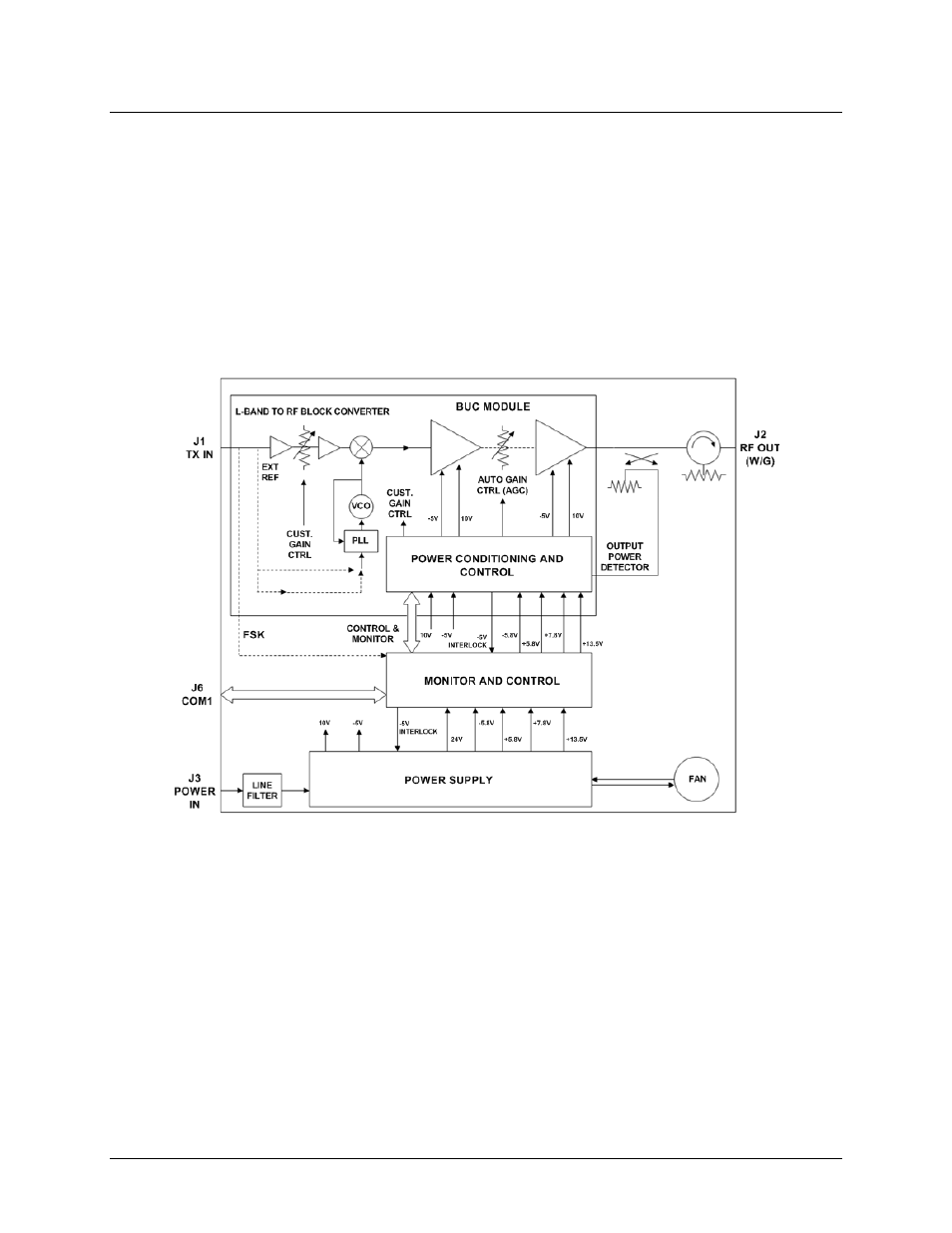
See Figure 1-2 for the LPOD-R block diagram. The major components of an LPOD-R unit are:
• SSPA Module
• Cooling System
• Monitor and Control (M&C)
• Power Factor Corrected Power Supply (PS 1 and PS 1.5 packages)
Figure 1-2. LPOD-R Typical Block Diagram
1.4.2
SSPA Module
The amplifier module performs the core function of the unit. An isolator is at the RF input to
ensure good voltage standing wave ratio (VSWR). The RF signal then passes through an
electronically controlled attenuator that adjusts the overall attenuation according to the user
input. After some amplification, a second attenuator is automatically controlled via a look-up
table to maintain the amplifier gain at a constant level over temperature variations.
The RF signal is then amplified by a multi-stage design that utilizes proprietary combining
techniques to meet the rated power requirements. The output circuitry contains a coupler to
provide a sampled signal for monitoring purposes. A power detector circuit also is included and
the reading can be accessed via remote communication. A high power circulator and load is
located at the output to provide good VSWR and protection from external mismatch.