2 lpod-r ps 1 j3 | power in dc power main option, 3 lpod-r ps 1.5 j3 | power in dc power main option, Table 2-3) – Comtech EF Data LPOD-R User Manual
Page 67
LPOD-R Outdoor Amplifier / Block Up Converter
MN-LPODR
System Connections, Installation and Startup
Revision 1
2–5
Table 2-3. LPOD-R PS 1 J3 | POWER IN Pin Assignments
Pin
LPOD-R PS .5 Assignment
A
V+
B
V-
C
GND (chassis ground)
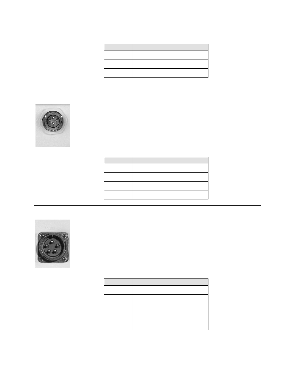
2.2.4.2 LPOD-R PS 1 J3 | POWER IN DC Power Main Option
The mating connector specification and the pin assignments (Table 2-4) unique to the
LPOD-R PS 1 DC power interface are as follows:
Mating Connector: CEFD P/N CN/STPG04F01 (Glenair IPT06E-12-4-SSR-F7)
Table 2-4. LPOD-R PS 1 J3 | POWER IN Pin Assignments
Pin
LPOD-R PS 1 Assignment
A
V+
B
GND
C
V-
D
NO CONNECT
2.2.4.3 LPOD-R PS 1.5 J3 | POWER IN DC Power Main Option
The mating connector specification and the pin assignments (Table 2-5) unique to the
LPOD-R PS 1.5 DC power interface are as follows:
Mating Connector: CEFD P/N CN-0020517 (MS3116E-14-5S(476), Amphenol PT06E-
14-5S(476))
Table 2-5. LPOD-R PS 1.5 J3 | POWER IN Pin Assignments
Pin
LPOD-R PS 1.5 Assignment
A
+48V
B
+48V
C
-48V
D
-48V
E
GND