1 lpod-r ps 1, ps 1.5 j3 | power in ac power main, 4 connector j3 | power in optional dc power mains, 1 lpod-r ps .5 j3 | power in dc power main option – Comtech EF Data LPOD-R User Manual
Page 66
LPOD-R Outdoor Amplifier / Block Up Converter
MN-LPODR
System Connections, Installation and Startup
Revision 1
2–4
• 47 to 63 Hz
The power supply is power factor corrected. The total power required from the prime power
supply depends on the model used. Please refer to Sect. 1.5 Summary of Specifications.
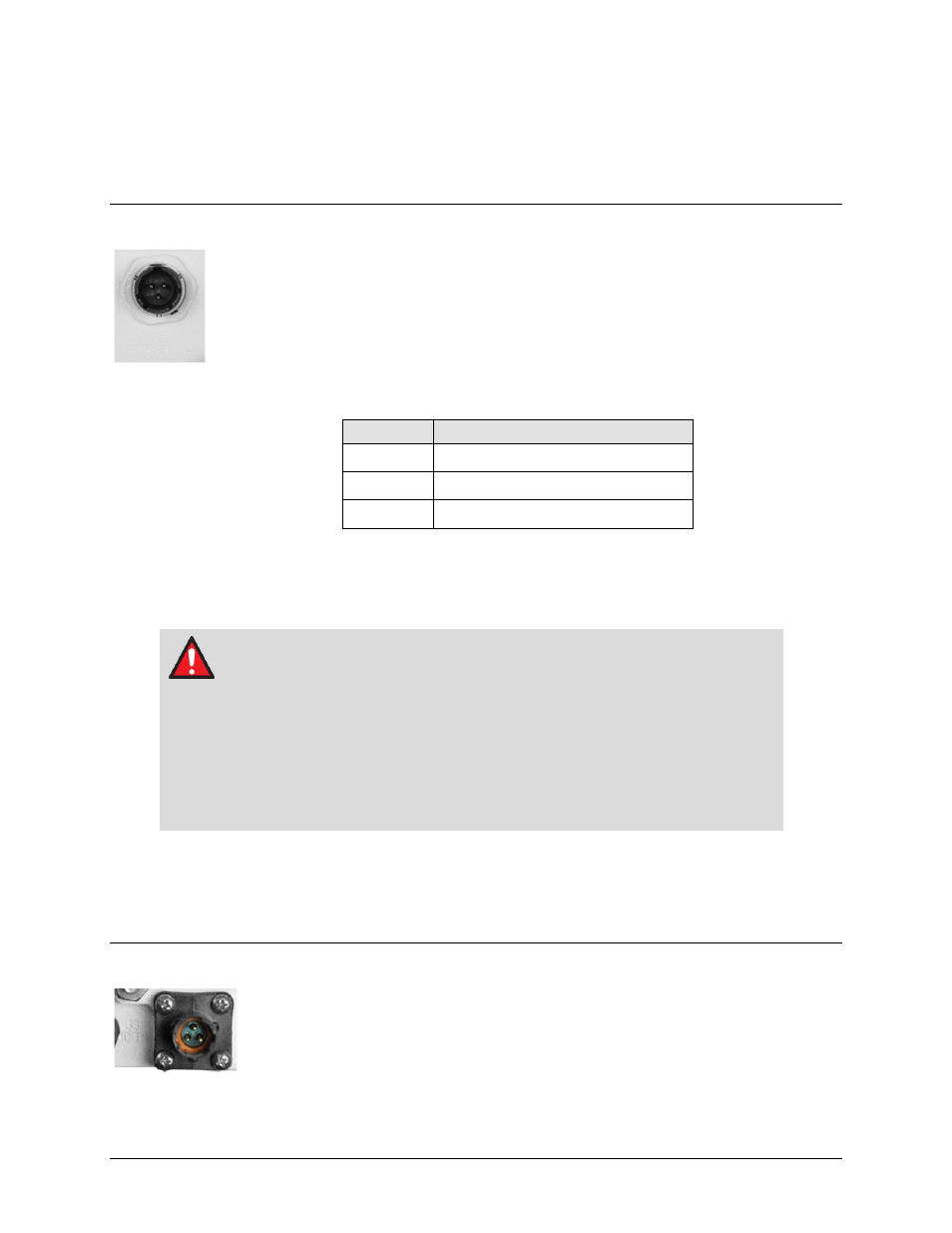
2.2.3.1 LPOD-R PS 1, PS 1.5 J3 | POWER IN AC Power Main
The mating connector specification and pin assignments (Table 2-2) unique to the LPOD-
R PS 1 and PS 1.5 AC power interfaces are as follows:
Mating Connector: CEFD P/N CN/MS-STPG03F02 (ITT Cannon KPT06B-12-35)
Table 2-2. LPOD-R PS 1/PS 1.5 J3 | POWER IN Pin Assignments
Pin
Description
A
LINE (L1)
B
NEUTRAL (L2)
C
GND
2.2.4 Connector J3 | POWER IN Optional DC Power Mains
Use of incorrect pin assignments can result in product damage or personal
injury.
For all LPOD-R models, the prime power input requirement is 36-72 VDC. The total power
required from the prime power supply depends on the model used. See Sect. 1.5 Summary of
Specifications for more information.
2.2.4.1 LPOD-R PS .5 J3 | POWER IN DC Power Main Option
The mating connector specification and pin assignments (Table 2-3) unique to the
LPOD-R PS .5 optional DC power interface are as follows:
Mating Connector: CEFD P/N CN-0020708 (SOURIAU UTS6JC8E33S)