4 set the lpod-r power on – Comtech EF Data LPOD-R User Manual
Page 74
LPOD-R Outdoor Amplifier / Block Up Converter
MN-LPODR
System Connections, Installation and Startup
Revision 1
2–12
2.4
Set the LPOD-R Power On
WARNING
For safety reasons, NEVER TURN THE UNIT ON WITHOUT PROPER WAVEGUIDE
TERMINATION ON THE J2 | RF OUT PORT. INDIVIDUALS CAN OTHERWISE BE
EXPOSED TO DANGEROUSLY HIGH ELECTROMAGNETIC LEVELS.
The LPOD-R does not contain a Power On/Off switch. It is powered ON by connecting the J3 |
POWER IN connector to the appropriate prime power source. The Mute or Transmit status of
the unit will automatically come up in the last stored state (factory default = Transmit on, not
muted).
2.4.1 Monitoring LPOD-R Operation with the LED Indicator (PS .5 ONLY)
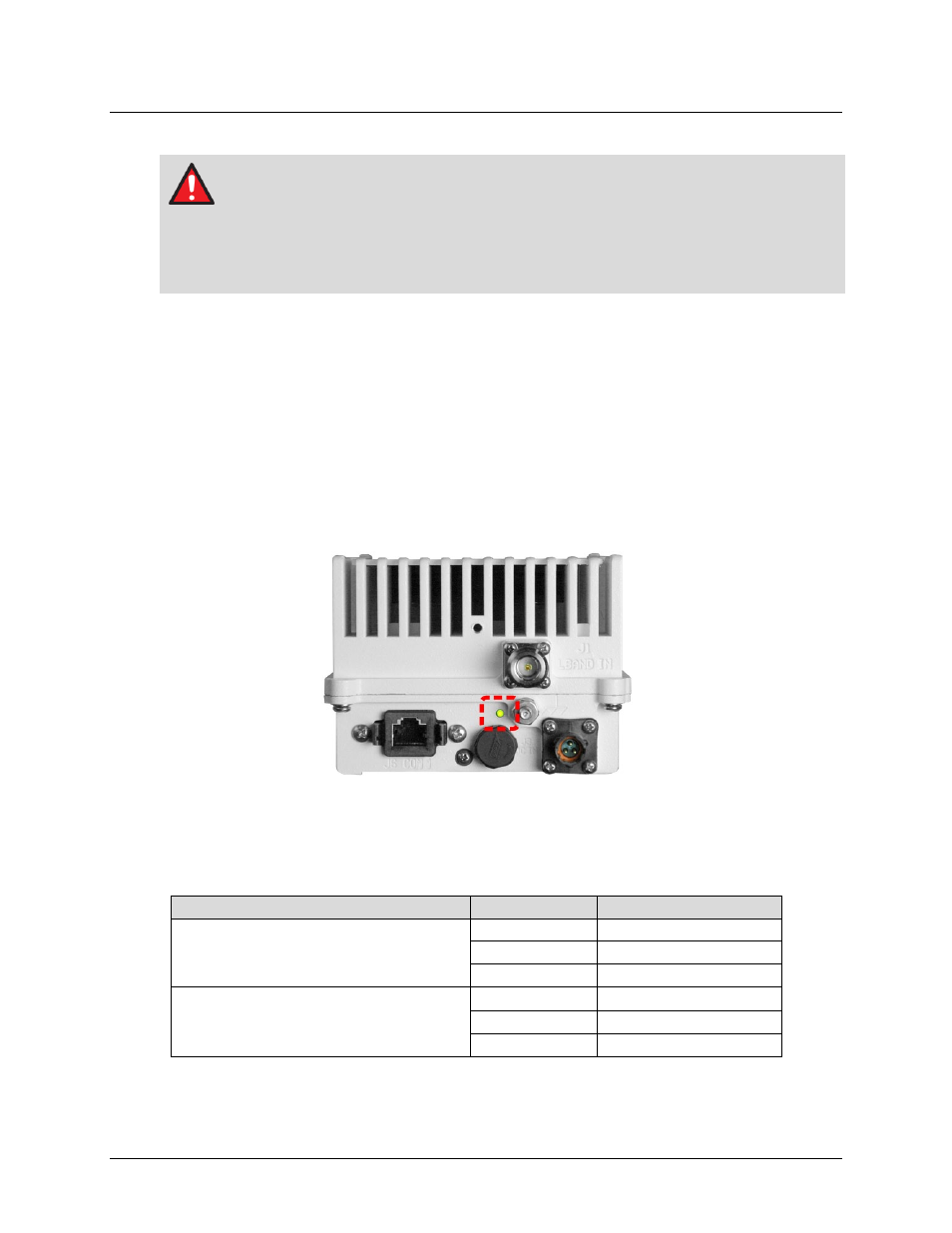
The LPOD-R PS .5 features a multi-color Light-Emitting Diode (LED) Indicator. Figure 2-8 shows
the location of this feature, on the signal output side of the LPOD-R PS .5 housing, next to the
ground lug. This LED provides you with visual cues to the operational status and LO setting for
the system.
Figure 2-8. LPOD-R PS .5 LED Indicator
A steadily-lit LED indicates that the unit is set for standard 14.0-14.5 GHz uplink frequency. A
blinking LED indicates that the unit is set for 13.75-14.5 GHz Tx frequency. Upon power-up of
the unit, the LED indicates operating status as per the following table:
OPERATING STATUS
LED COLOR
UNIT STATE
Standard
14.0-14.5 GHz Uplink Frequency
Green
Unmuted, 13.05 GHz LO
Yellow
Muted, 13.05 GHz LO
Red
Faulted, 13.05 GHz LO
13,.75-14.5 GHz Tx Frequency Operation
Green (blinking) Unmuted, 12.8 GHz LO
Yellow (blinking) Muted, 12.8 GHz LO
Red (blinking)
Faulted, 12.8 GHz LO