2 interface connectors, 1 connector j1 | lband in, 2 connector j2 | rf out – Comtech EF Data LPOD-R User Manual
Page 65: 3 connector j3 | power in ac power mains
LPOD-R Outdoor Amplifier / Block Up Converter
MN-LPODR
System Connections, Installation and Startup
Revision 1
2–3
2.2
Interface Connectors
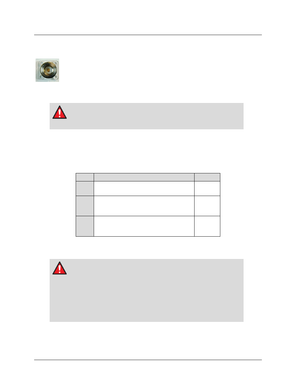
2.2.1 Connector J1 | LBAND IN
The J1 | LBAND IN RF input connector is a Type N female connector. Typical input levels (-
30 dBm) depend on desired output power and unit attenuation. To prevent damage to the
LPOD-R, RF input levels must not exceed +15 dBm.
2.2.2 Connector J2 | RF OUT
WARNING
For safety reasons, never look directly into the waveguide output.
The J2 | RF OUT connector may be a waveguide or coaxial interface – the type of interface used
depends on the LPOD-R model and/or frequency range of the unit, as described in Table 2-1 and
as shown in Figures 2-1, 2-2, and 2-3.
Table 2-1. J2 | RF OUT Interface Type
Unit
Frequency / Output Type
Figure
PS .5
C-Band: CPR137G
Ku-Band: WR75G
PS 1
C-Band: Type N Female (optional CPR137G)
X-Band: CPR112G
Ku-Band: WR75G
PS 1.5
C-Band: CPR137G
X-Band: CPR112G
Ku-Band: WR75G
2.2.3 Connector J3 | POWER IN AC Power Mains
WARNING
For safety reasons, make sure you know that the J3 AC Power Connection pin
assignments for each LPOD-R model are different. You must use the correct
pin assignments.
Use of incorrect pin assignments can result in product damage or personal
injury.
For any AC-powered LPOD-R product, the prime power input requirement is as follows:
• 90-264 VAC