3 cooling system, 4 monitor and control (m&c), 5 power supply – Comtech EF Data LPOD-R User Manual
Page 54
LPOD-R Outdoor Amplifier / Block Up Converter (BUC)
MN-LPODR
Introduction
Revision 1
1–4
1.4.3
Cooling System
The PS .5 contains a single fan that is always enabled. The PS 1 contains one temperature-
controlled fan, and the PS 1.5 contains two temperature-controlled fans.
1.4.4
Monitor and Control (M&C)
The LPOD-R includes a microprocessor-based system that provides monitoring and control of
the essential parameters of the unit. You interface with the unit through the M&C system via
the remote control/discrete communications port. The unit is capable of Ethernet remote
communication, while EIA-232/485 is optional on the PS 1 and PS 1.5 packages. A discrete mute
control and relay status output is also available on the PS 1 and PS 1.5 packages.
The M&C system monitors the fan speed, unit temperature, all power supply voltages, power
transistor currents, output power, etc. Should a critical monitored parameter fail, the unit will
mute the RF signal and report a fault. The details of the fault can be accessed via remote
communication.
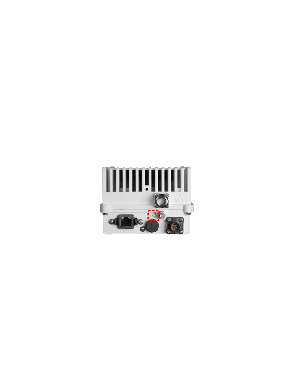
The LPOD-R PS .5 features a Light-Emitting Diode (LED) Indicator. Figure 1-3 shows the location
of this feature, on the signal output side of the LPOD-R PS .5 housing, next to the ground lug.
This LED provides you with visual cues to the operational, online, and offline status of the
system. See Chapter 2 for complete details about interpreting LED operation.
Figure 1-3. LPOD-R PS .5 LED Indicator
1.4.5
Power Supply
The LPOD-R features a power supply that is power factor corrected. It supplies several voltages
necessary for the unit to operate:
The 10V power supply output state is controlled by circuitry within the RF module. If the RF
module does not have the –5.8V supply for any reason, it will not allow the 10V power supply to
turn on. This protects the power transistors within the RF module from failure due to improper
power supply sequencing.
The +24V output powers the cooling fans, is the source of power for waveguide switching when
the SSPA is used in redundant configurations, and is dropped to +22V for LNB bias.
The +5.8V, -5.8V, +7.8V and +13.5V outputs are used to operate the M&C board and other
overhead functions.