Flowserve MX Limitorque User Manual
Page 105
Advertising
97
Limitorque MX Maintenance and Spare Parts FCD LMENIM2314-00 – 07/08
flowserve.com
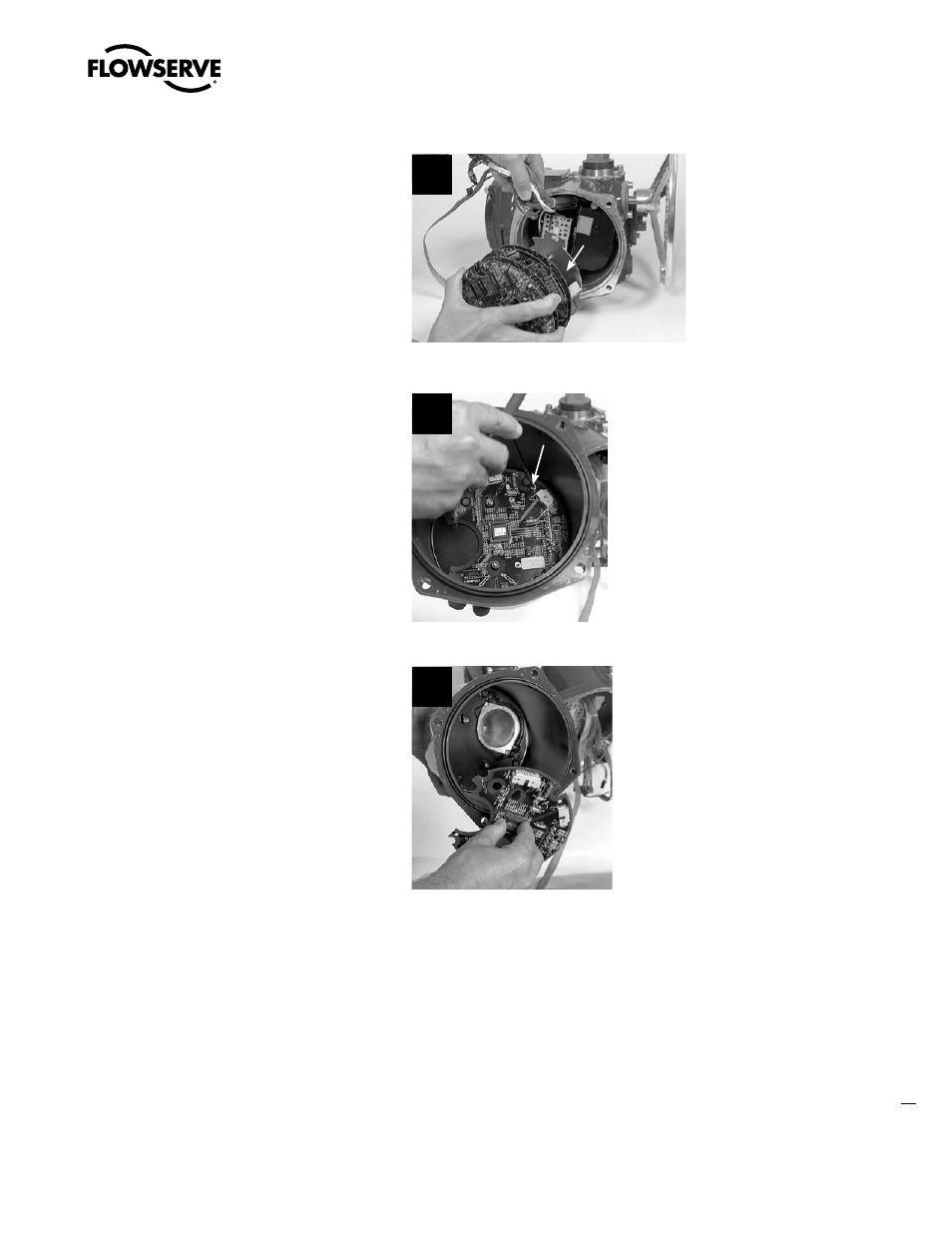
STEP 7
Remove the control module assembly from
actuator housing (leave 20-pin ribbon cable
connected to control module boards). Take
control module assembly to work area to
perform maintenance as required.
If control module assembly return is required
for repair/replacement, remove the CP board
from inside the CP cover as follows:
7
Integral
Controls
Assembly
STEP 8
Using a 3 mm hex key, remove the four M4
screws (#8-25) that retain the CP board inside
the CP cover.
8
8-25
STEP 9
Lift the CP board out of the CP cover.
(See Section 5.2.3 for fuse replacement.)
(See Section 5.2.4 for control module return
options.)
(See Section 5.2.5 for EPROM care and
replacement.)
9
Advertising
This manual is related to the following products: