Flowserve MX Limitorque User Manual
Page 52
Advertising
Limitorque MX Maintenance and Spare Parts FCD LMENIM2314-00 – 07/08
44
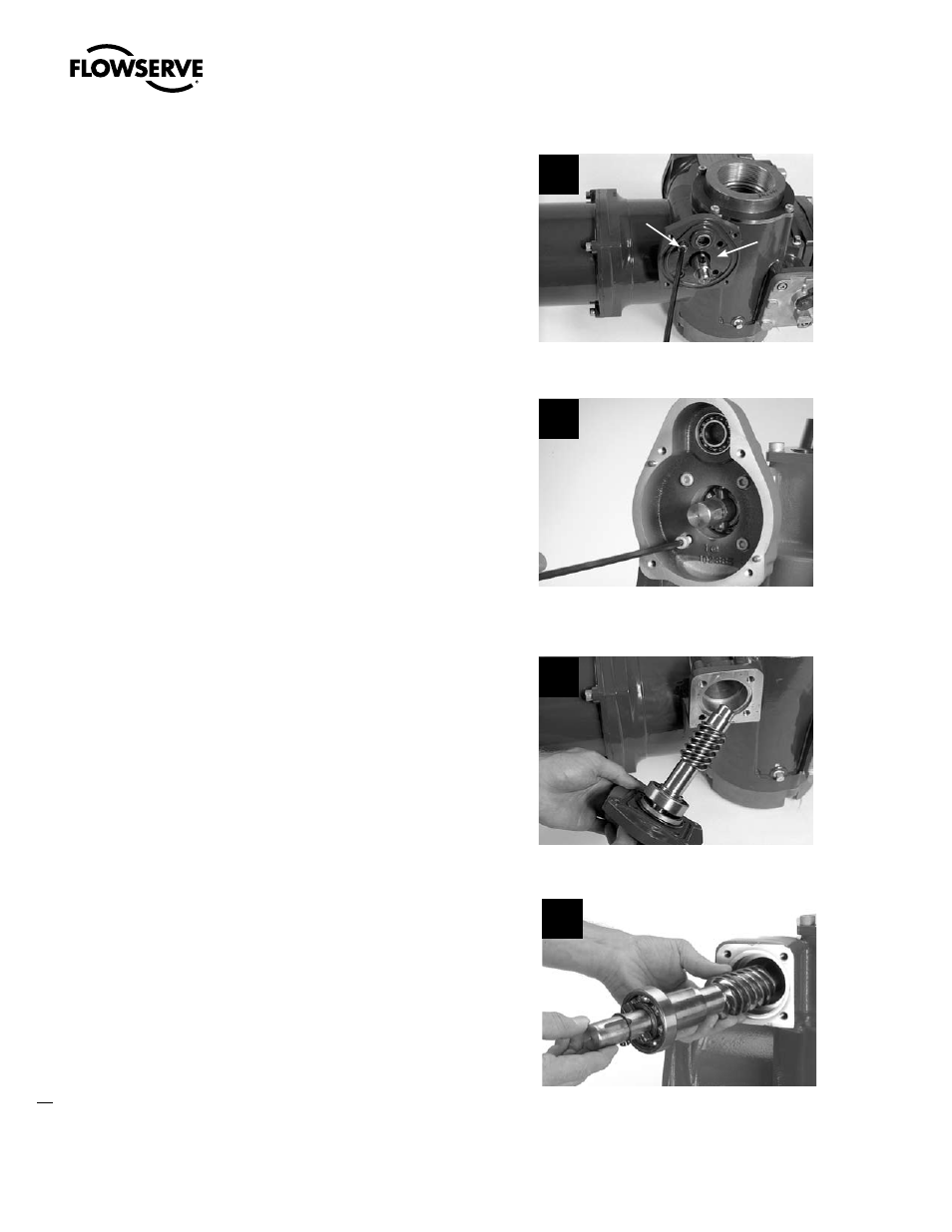
STEP 4
Remove the four M6 screws (#13-9) from the
worm shaft plate (#13-2).
4a
13-2
13-9
MX-40
4b
MX-85/140/150
STEP 5
Removing worm shaft assembly.
MX-40: Remove adapter plate and worm
assembly together (5a).
MX-85/140/150: Remove adapter plate, then
remove worm assembly (5b).
NOTE: When removing the side-mounted
handwheel, the inner bearing (#13-8) should
remain in place in the housing.
Rotate the handwheel assembly clockwise
(CW) to withdraw the complete worm shaft
plate subassembly.
5a
MX-40
5b
MX-85/140/150
Advertising
This manual is related to the following products: