Flowserve MX Limitorque User Manual
Page 30
Advertising
Limitorque MX Maintenance and Spare Parts FCD LMENIM2314-00 – 07/08
22
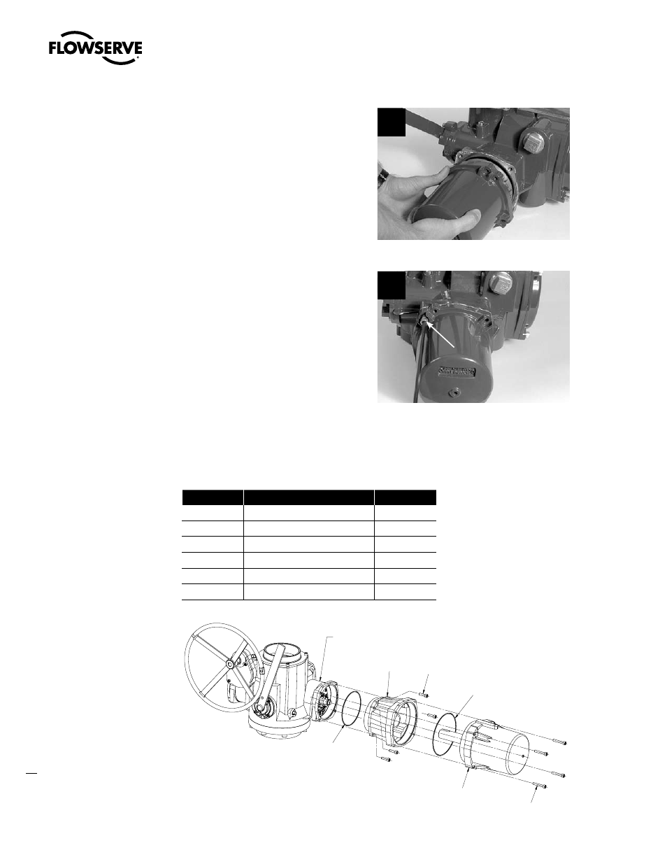
STEP 7
Push the rotor shaft onto the protruding
worm shaft, aligning the rotor shaft slots with
the worm shaft pin. Slide the motor housing
spigot/pilot into the actuator housing.
7
STEP 8
Fit the four screws (#1-14) into the motor
subassembly mounting holes and tighten.
8
1-14
4.1.3 Removal and mounting of MX-140 motor
(40 RPM and greater)
Table 4.2 – Motor Parts List
Part Number
Description
Qty.
1-14
Socket head cap screw
4
1-15
O-ring
1
4-7
Motor
1
4-8
Adapter, motor
1
4-9
Socket head cap screw
4
4-10
O-ring
1
Figure 4.2 – Motor and Adapter (MX-140)
MAIN UNIT ASSEMBLY
4-8
1-14
4-10
1-15
4-7
4-9
Advertising
This manual is related to the following products: