Flowserve MX Limitorque User Manual
Page 133
125
Limitorque MX Maintenance and Spare Parts FCD LMENIM2314-00 – 07/08
flowserve.com
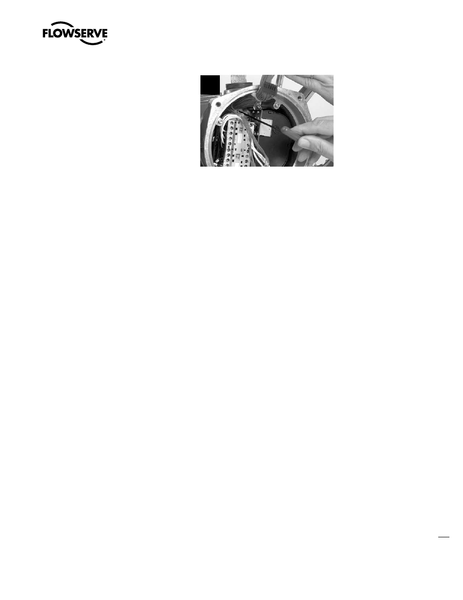
STEP 8
Position the contactor assembly so that the
keyhole slots in the contactor mounting plate
allow the M4 screw heads to pass through;
shift the contactor assembly until the screw
heads seat in the key slots. Tighten screws
using 3 mm hex key to secure assembly.
8
STEP 9
Remount all removed subassemblies according to the remounting instructions in the following
order:
1. Terminal block (subassembly #15). (See Section 5.8.2.)
2. Control module (subassembly #8). (See Section 5.2.2.)
3. Control panel (subassembly #7). (See Section 5.1.)
4. Motor (subassembly #4). (See Section 4.1.2.) If the motor voltage has changed, please see
Section 5.2.3, Step 10 to ensure the voltage jumper on the power board is located in the proper
slot.
5.11 Replacing 19 Amp Reverser on the MX-140
and -150 (Not for most actuators shipped
after September 2007)
STEP 1
Follow the steps in 5.10.1. Remove control cover and disconnect the encoder and controls package.
Remove controls package from MX housing.
STEP 2
Remove terminal cover, retaining ring, terminal block and O-ring to access the back of the terminal
block.