Flowserve MX Limitorque User Manual
Page 94

Limitorque MX Maintenance and Spare Parts FCD LMENIM2314-00 – 07/08
86
STEP 8
NOTE: Retainer plate (#1-32) may sit slightly above actuator housing until screws are retightened.
c
WARNING: The MX-10 through -150 require precaution to prevent damage to the
declutch latch. This applies while installing the handwheel adapter/gear assembly
(#1-35), retainer plate (#1-32) and screws (#1-33). If the unit is in the clutched position
(handwheel operation) during assembly, a lug-to-lug condition can result between the
clutch and the handwheel adapter/gear. In this situation the latch will be compressed
and damaged when the plate screws are tightened.
Assure the clutch lugs are fully engaged to the
bronze gear lugs before installing the hand-
wheel adapter/gear assembly. The latch must
be rotated down and not holding the clutch
off the bronze worm gear. When installing the
handwheel adapter/gear, ensure these lugs fall
between the clutch lugs. This position will allow
the handwheel adapter/gear lugs to be fully
engaged to the clutch lugs. The final step is to
install the retaining plate and socket head cap
screws.
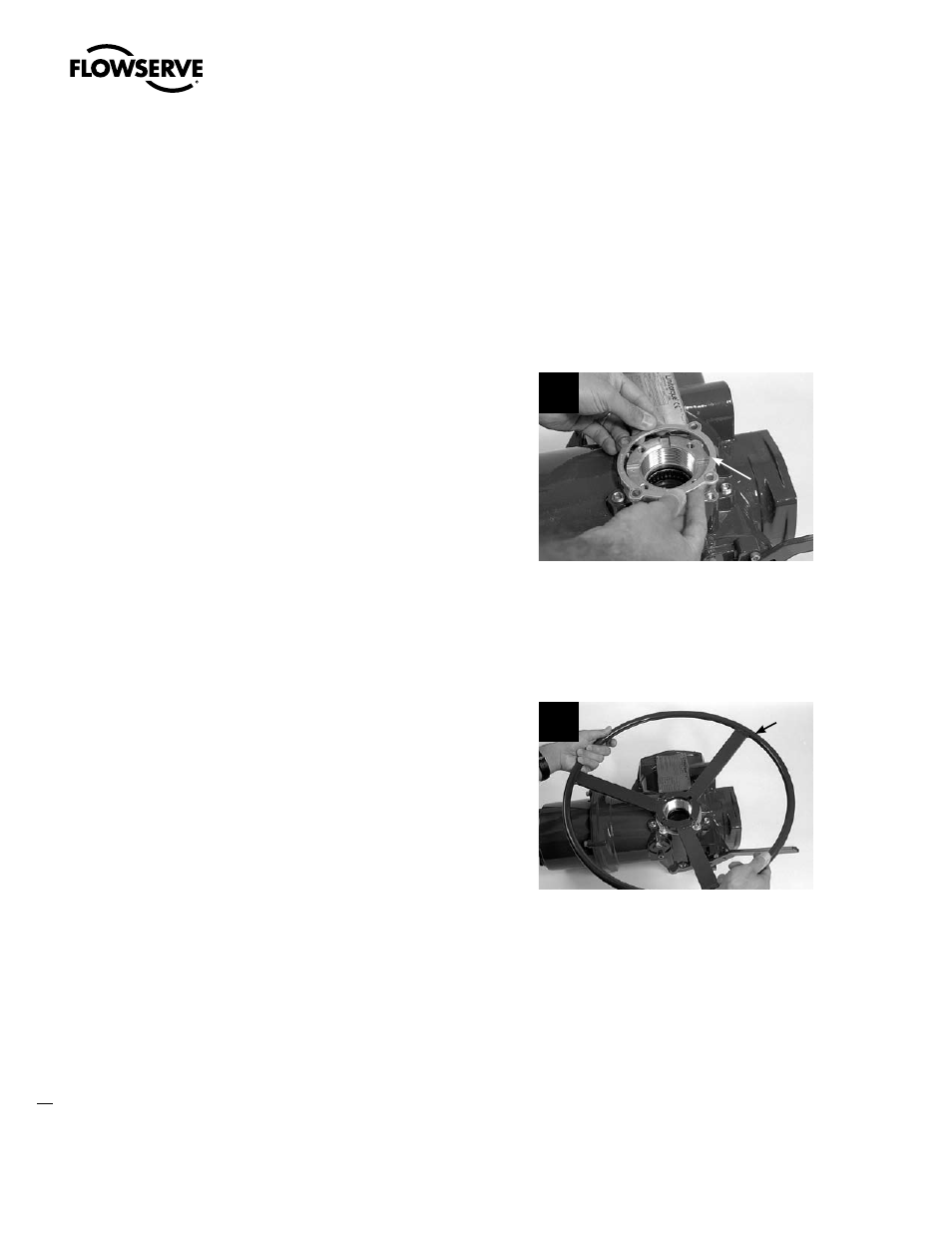
Place the retainer plate (#1-32) on the top of
the actuator housing. Align the mounting taps,
and secure with screws (#1-33).
8
1-32
STEP 9 (MX-10, -20 AND -40)
Install handwheel (#1-8) onto handwheel
adapter assembly (#12), align the handwheel
with screw holes and tighten the four socket
head cap screws (#1-11).
or
Install side-mounted handwheel (subassembly
#13) according to remounting instructions
detailed in Section 4.4.3.
9
1-8