7a 7b – Flowserve MX Limitorque User Manual
Page 39
31
Limitorque MX Maintenance and Spare Parts FCD LMENIM2314-00 – 07/08
flowserve.com
STEP 6 (MX-85, -140, AND -150 ONLY)
Set screw adjustment. Install drive sleeve, baseplate, clutching and handwheel worm gear compo-
nents. Assure the clutch lugs are fully engaged to the motor worm gear lugs before the adjustment.
With declutch lever resting on cap pad (not the set screw) place declutch cap assembly (1-4) into
housing without mounting screws. Rotate cap assembly clockwise until declutch cam is resisted
by the roller, clutch ring and clutch combination. Holding the declutch lever, rotate the set screw
clockwise through declutch cap, (this will rotate the cap counterclockwise) until the cap mounting
holes are inline with the taps in the housing. Install declutch assembly mounting screws. Then
rotate set screw counterclockwise 1/4 turn, plus or minus
1
⁄
8
turn. Adjustment is complete.
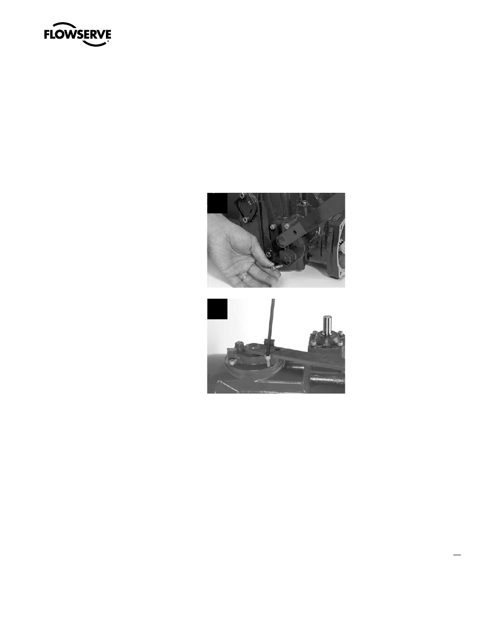
STEP 7
Fit the two M6 (MX-05 and -10) screws
(#5-12), M8 (MX-20 and -40) screws to retain
the declutch assembly cover (#5-1) on the
housing. Tighten using a 5 mm (MX-05 and
-10) or 6 mm (MX-20, -40 and -85) hex key.
Picture 7a shows the two screws for the MX-20
and -40. Picture 7b shows the four screws for
the MX-85.
See picture 7a for MX-05, -10, -20 and -40. See
picture 7b for MX-85, -140, and -150.
7a
7b
STEP 8 (MX-20 AND -40 ONLY)
Remount the following subassemblies after remounting the declutch assembly.
(See corresponding referenced sections for remounting information.)
1. Handwheel (subassembly #13). (See Section 4.3.2.)
2. Handwheel adapter (subassembly #12). (See Section 4.4.2, 4.4.3, and 4.5.3.)
3. Clutch and clutch ring (subassembly #16). (See Section 4.15.2.)