Error codes – Hypertherm HT200LHF-200 Volt HySpeed User Manual
Page 103
Number
of blinks
Explanation
1
Indicates that the IHS Complete signal has not been
returned within 30 seconds after the plasma START
command has been given.
2
Indicates that an "interlock" error has occurred.
3
Indicates that the HOLD input (for multi-torch systems) was
not released within 30 seconds after the end of preflow.
4
Indicates that there was no transfer within 300ms.
5
Indicates that transferred current arc was lost during
ramp up.
6
Indicates that the current was lost from chopper #1 (CH1).
7
Indicates that the current was lost from chopper #2 (CH2).
8
Indicates that transferred current arc was lost during ramp
down.
9
Indicates that the software has an error.
10
Indicates that the input voltage has dropped below 15% of
the nominal value. Eg: Input voltage for a 480V power
supply drops below 408V.
MAINTENANCE
5-14
HySpeed HT2000LHF
Instruction Manual
7
Error Codes
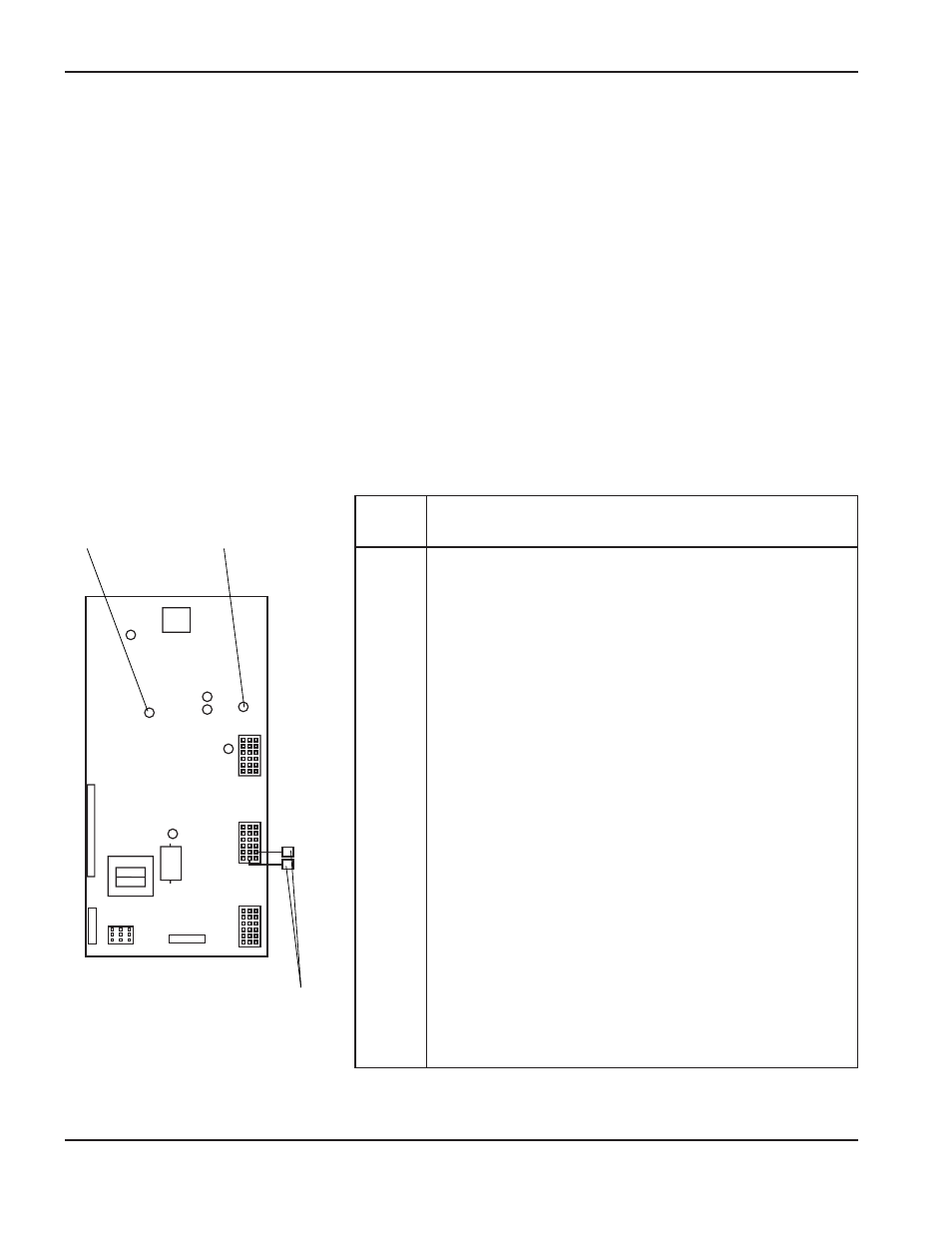
The microcontroller on control board PCB2 will alert the user when certain errors occur in the system, by flashing
the Error Code LED on the control board . The power supply front cover must be removed to observe control board
PCB2 and the Error Code LED (see Figure 6-1 for location of PCB2 and Figure 5-5 for location of Error Code LED
on PCB2).
The Error Code LED will blink on for .5 seconds and off for .5 seconds with a 2-second gap before repeating the
blinking sequence. The number of blinks between the 2-second gap is 1 of 10 error indications listed below.
During the error code flashing, all outputs from the control board are turned off, and the power supply is in an idle
mode. After the error is corrected, you may resume operation of the system.
Note: 8 or 9 blinks will occur during normal operation. If the Error Code LED remains on without blinking, this
indicates that a microcontroller internal RAM or ROM self-check error has occurred (power supply will
hang up).
For troubleshooting purposes, the Plasma Start LED is also shown in Figure 5-5. When illuminated, this LED
indicates that the plasma START command has been received at the control board.
Figure 5-5
Control Board Error Code LED Location and Code Explanation
Terminals are normally disconnected.
ERROR CODE
LED
PLASMA START
LED