Turn gases on, Turn power supply on and adjust voltage & current, Adjust preflow gases – Hypertherm HT200LHF-200 Volt HySpeed User Manual
Page 61: Air (for nitrogen or air as plasma gas), or o, Hyspeed, Ht2000lhf
OPERATION
4-8
HySpeed HT2000LHF
Instruction Manual
6
Turn Gases On
4. Set S2 toggle switch on the gas console to Run
.
5. Set S1 on the gas console to N
2
/Air (for nitrogen or air as plasma gas), or O
2
(for oxygen as plasma gas).
6. Turn the required supply gases On
.
Note: See the
Cut Charts
to set the plasma and shield gas inlet pressures.
Turn Power Supply On and Adjust Voltage & Current
7. Turn the main disconnect switch ON. See
Status Indicators Before Startup
earlier in this section.
8. Turn on the power supply by depressing and holding down the POWER ON (I) button (PB1) on the power
supply. Ensure that the green POWER ON indicator illuminates. Hold PB1 down until all of the status indicators
extinguish.
9. Set the voltage and current from the Digital Remote Voltage and Current Console or from the machine computer
interface. Select the arc current and arc voltage from the
Cut Charts
for the type and thickness of metal to cut.
PLASMA
N
2
/Air
O
2
SHIELD
N
2
/Air
psi
psi
psi
DC
N
2
/Air
O
2
O
2
PLASMA
Cut Flow
PreFlow
PreFlow
Run
10
9
8
7
6
5
4
3
2
1
0
10
9
8
7
6
5
4
3
2
1
0
Test
Preflow
Test
Cutflow
HySpeed
®
HT2000LHF
®
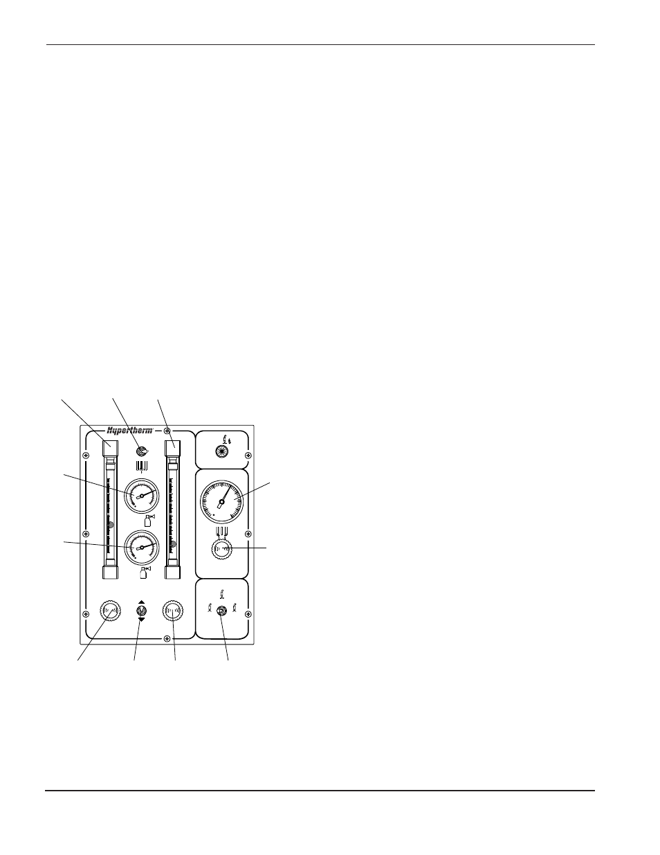
Adjust Preflow Gases
10. Set S2 on the gas console to Test Preflow. Verify the
plasma gas inlet pressure reading on the plasma
pressure gauges (PG1, PG2) on the gas console.
Refer to the
Cut Charts
for the proper pressure
setting.
11. Look at the oxygen (FM2) and/or nitrogen-air (FM1)
flowmeters on the gas console and set the Preflow
plasma gas flow rate % by referring to the
Cut Charts
and turning the oxygen (MV3) and/or nitrogen / air
(MV2) preflow metering valves.
12. Look at the shield gas pressure gauge (PG3) on the
gas console, and set to the
Cut Chart
specifications
by turning the shield gas metering valve (MV4).
Note: If you have changed consumable parts or if the
power supply has been off for more than 1 hour,
purge gas lines by leaving system in Test Preflow
for 1 minute.
FM1
PG1
PG2
PG3
MV4
S1
FM2
MV2
MV1
MV3
S2