Wiring diagram symbols – Hypertherm HT200LHF-200 Volt HySpeed User Manual
Page 130
HySpeed HT2000LHF
Instruction Manual
7-1
6
Section 7
WIRING DIAGRAMS
Introduction
This section contains the wiring diagrams for the HT2000LHF system. When tracing a signal path or referencing
with the
Parts List
or
Troubleshooting
sections, please be aware of the following format to assist you in under-
standing the wiring diagrams' organization:
• Sheet numbers are located in the lower right-hand corner.
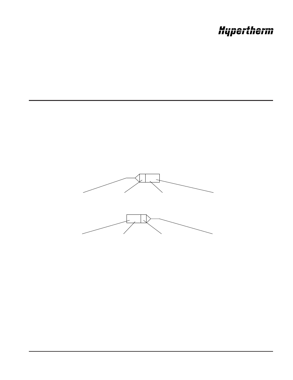
• Page-to-page referencing is done in the following manner:
C
SHEET
4-D3
C
SHEET
4-D3
Destination
and
Source Coordinates
refer to letters A-D on the Y-axis of each sheet and numbers 1-4 on the
X-axis of each sheet. Lining up the coordinates will bring you to the source or destination blocks (similar to a road
map).
• When referencing components to the wiring diagrams, designations may appear to be repeated. Eg. C1
appears on sheet 2 in the wiring diagrams in 2 locations. Sections of the power supply on that page are
outlined with a dotted box and a label. Within different sections, the same designation may appear. Be
certain to check the dotted box label when looking for or cross-referencing HT2000LHF parts.
Wiring Diagram Symbols
Wiring diagram symbols and their identification precede the system wiring diagrams in this section.
Source Connection
Source Reference Block
Destination Sheet #
Destination
Coordinates
Source Sheet #
Source Coordinates
Source Reference Block
Destination
Coordinates