Hypertherm HT200LHF-200 Volt HySpeed User Manual
Page 187
IHS Air Supply – Air Supply to IHS Console
The customer must supply the 20 psig (1.4 bar) regulated shop air and a 1/4" (6 mm) I.D. air hose between
the regulator and the inductive height control console.
Air Hose Assembly – IHS Console to Inductive Sensor Air Cylinder
The 40-foot air hose is a component of the interconnecting leads for the inductive IHS system – see page c-4.
APPENDIX C: INITIAL HEIGHT SENSING CONNECTIONS
HySpeed HT2000LHF
Instruction Manual
c-3
6
14B
14B
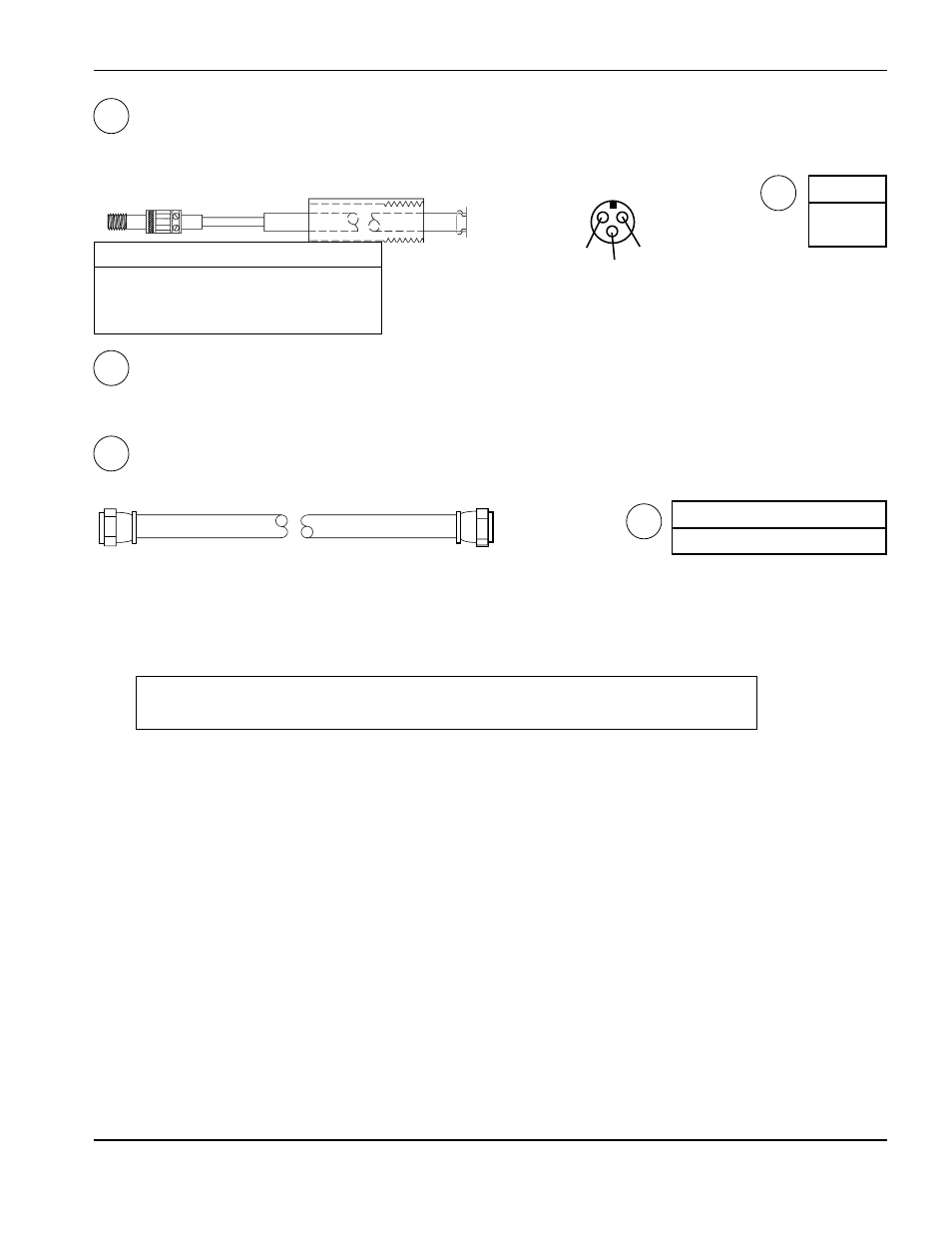
IHS Inductor Probes
The 2 inductive probes come with the torch mounting subassembly for the inductive IHS system – see page c-4.
14C
14D
14D
Part No.
005074
A
B
C
Rear View
Pin
Color
Signal
A
Brown
Power (+15 VDC)
B
Blue
Common
C
Black
Signal
Part No.
Length
024144
40 ft (12 m)
Upper Limit Switch and Cable - Upper Limit Switch to IHS Console
Note:
The customer must supply the upper limit switch option.
Switch specifications: +12 VDC @ 1.2 ma.
Gold-type contacts preferred. Select a normally closed switch that opens when the lever is up (when the
torch fully retracts). Install the upper limit switch behind the torch lifter as in Figure c-1.
Caution:
Follow the cable installation procedure below to avoid electromagnetic
interference problems with the torch lead set.
1. Use a shielded, twisted pair of 22-24 gauge wire (stranded). Use Belden #8761.
2. At the upper limit switch, connect the common wire (black) and signal wire (clear) to the upper limit switch. Cut
the shield drain wire (uninsulated). Wrap the cut end with electrician's tape.
3. At the IHS control console, loosen the 2 latches and open the front cover.
4. Route the cable through the strain relief to connect the cable wires to 1TB.
5. Connect the shield drain wire (uninsulated) to 1TB-10 (#S). This connects the cable shield to the power supply
frame. The shield drain must not touch the IHS console case.
6. Connect the common wire (black) to 1TB-11 (#4).
7. Connect the signal wire (clear) to 1TB-12 (#67).
Note: If the upper limit switch signal comes from an interface on the cutting machine, the shield must be
electrically isolated from other shields in other cables. Use a separate cable to avoid ground-loop
problems.