Verilink 8100A (34-00237) Product Manual User Manual
Page 160
4-86
8 0 0 0 S e r i e s
from being linked. However, the High POTS Port IAD’s Frame Relay-to-ATM
Network/Service Interworking (FRF.5/FRF.8) feature allows Frame Relay and
ATM networks to exchange data, despite differing network protocols. The func-
tional requirements for linking Frame Relay and ATM networks are provided by
the Frame Relay/ATM PVC Network/Service Interworking Implementation
Agreement specified in Frame Relay Forum (FRF) document numbers FRF.5
and FRF.8. Before setting the interworking options, you must first configure the
Frame Relay options for the USI port, and the ATM options for the WAN port.
Interworking can be configured to support FRF.5 or FRF.8 and will support a
maximum of four VCs. When FRF.5 or FRF.8 interworking is configured on
a PVC or DLCI, it is switched at the Layer 2 level. Data does not go up the
IP or bridge stacks, so configuring bridging or an IP address on an
interworked PVC or DLCI is not possible. FRF.8 Frame/ATM service
Interworking maps Frame datalink connection identifiers (DLCIs) to ATM
permanent virtual circuits (PVCs). FRF.5 provides network Interworking
functionality that allows Frame Relay end users to communicate over an
intermediate ATM network.
NOTICE:
When configuring the Network port and the USI port, it is important to
ensure the correct encapsulations are used. On the Network port, use
RFC 1483(with LLC Encapsulation) PVCs. On the USI port, RFC 1490
DLCIs are valid for interworking.
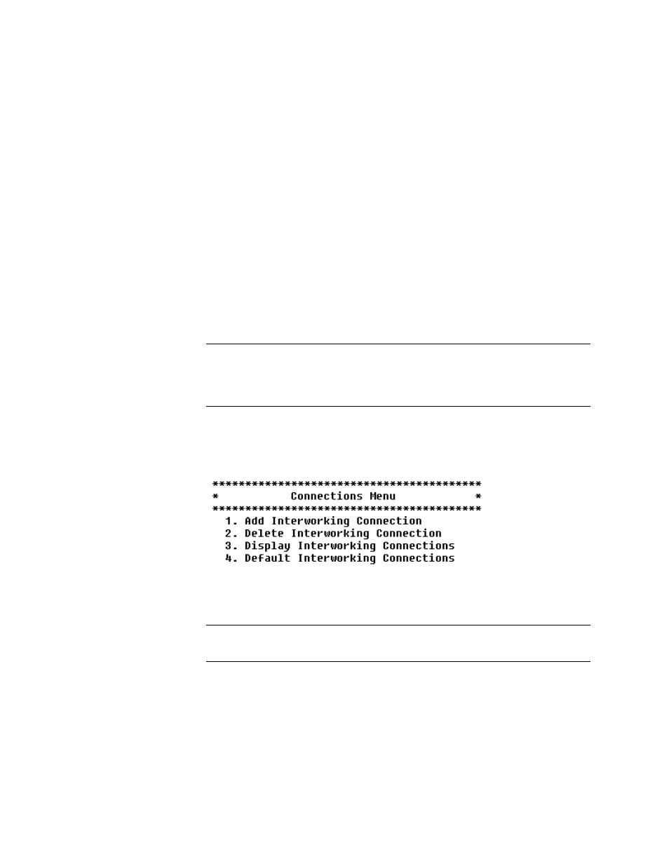
To access the Interworking feature, select “I” on the Main menu, which will
display the Connections menu shown in Figure 4.102.
Figure 4.102
Connections Menu
Select select “1” to add an Interworking Connection. The following menu
will be displayed:
NOTICE:
You must have configured at least one Frame Relay DLCI and one ATM
PVC to use the Interworking feature.
- 8108 Series IAD (34-00339.B) Product Manual 8508 Series IAD (34-00339.B) Product Manual 8208 Series IAD (34-00339.B) Product Manual 8308 Series IAD (34-00339.B) Product Manual 7500p Series IAD (34-00334.B) Product Manual 7200p Series IAD (34-00334.B) Product Manual 7000 Series (34-00334) Product Manual