2 explanation of the error tables – SMA SC 500CP-10-JP User Manual
Page 77
SMA Solar Technology AG
10 Troubleshooting
User Manual
SCCP-JP-BA-A4-en-12
77
• System-Specific
The Sunny Central switches to the operating state "Fault" and opens the AC contactor and the DC switchgear.
The Sunny Central does not feed into the grid. How long the Sunny Central remains in this state depends on
system-specific influencing factors.
Once the time has elapsed, the disturbance is no longer shown on the touch display. The Sunny Central then checks
whether the cause of the error has been rectified. If the disturbance is no longer pending, it is deleted from the
memory.
• Warning
A warning does not affect the behavior of the Sunny Central. The cause of the warning must be established and
remedied.
In the operating state "Disturbance", the error, error number, error message and a symbol are displayed on the touch
display (see Section 10.2.1 "Reading Off Disturbance Messages via Touch Display", page 75).
Once the cause of the disturbance has been rectified and the disturbance is no longer displayed, it is deleted from the
fault memory. To view previous disturbances after they have been deleted from the fault memory, an event report is filed
on the SD memory card. The event report logs the time and type of disturbance. The event report can also be displayed
on the user interface.
Depending on the type of disturbance, a reset may be performed. When this happens, the relays are checked and the
voltage supply to the control system is switched off. This process takes less than one minute. While the control system is
booting, the regular waiting times for grid monitoring are complied with.
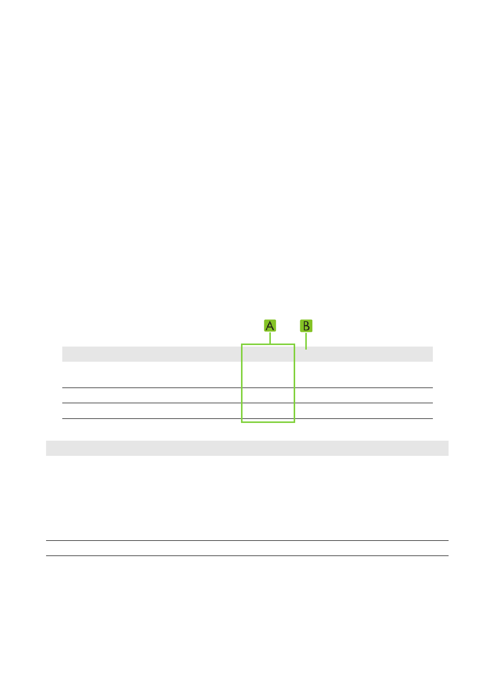
10.4.2 Explanation of the Error Tables
You will find the following information in the error tables in Sections 10.4.3, 10.4.4 and 10.4.5:
Figure 34: Structure of error table (example)
Position
Explanation
A
Behavior of the Sunny Central: error level S1, error level S2
s / min: waiting time
C: system-specific
D: day change
Q: waiting for acknowledgement
W: warning
B
Reset
Error no.
Explanation
S1
S2
R
Corrective measures
1301
Left rotating magnetic field is
connected.
30 s
Q
‒
• Check phase angle.
3803
DC current of PV array is too high.
1 min
D
x
• Check DC input current.
0104
Line voltage is too high.
W
C
‒
• Check line voltage.