Connections – Precision Digital PD6730X User Manual
Page 16
PD6730X Vantageview Super Snooper Modbus Scanner
Instruction Manual
16
Connections
WARNINGS
Static electricity can damage sensitive components.
Observe safe handling precautions for static-sensitive components.
Use proper grounding procedures/codes.
If the scanner is installed in a high voltage environment and a fault or installation error
occurs, high voltage may be present on any lead or terminal.
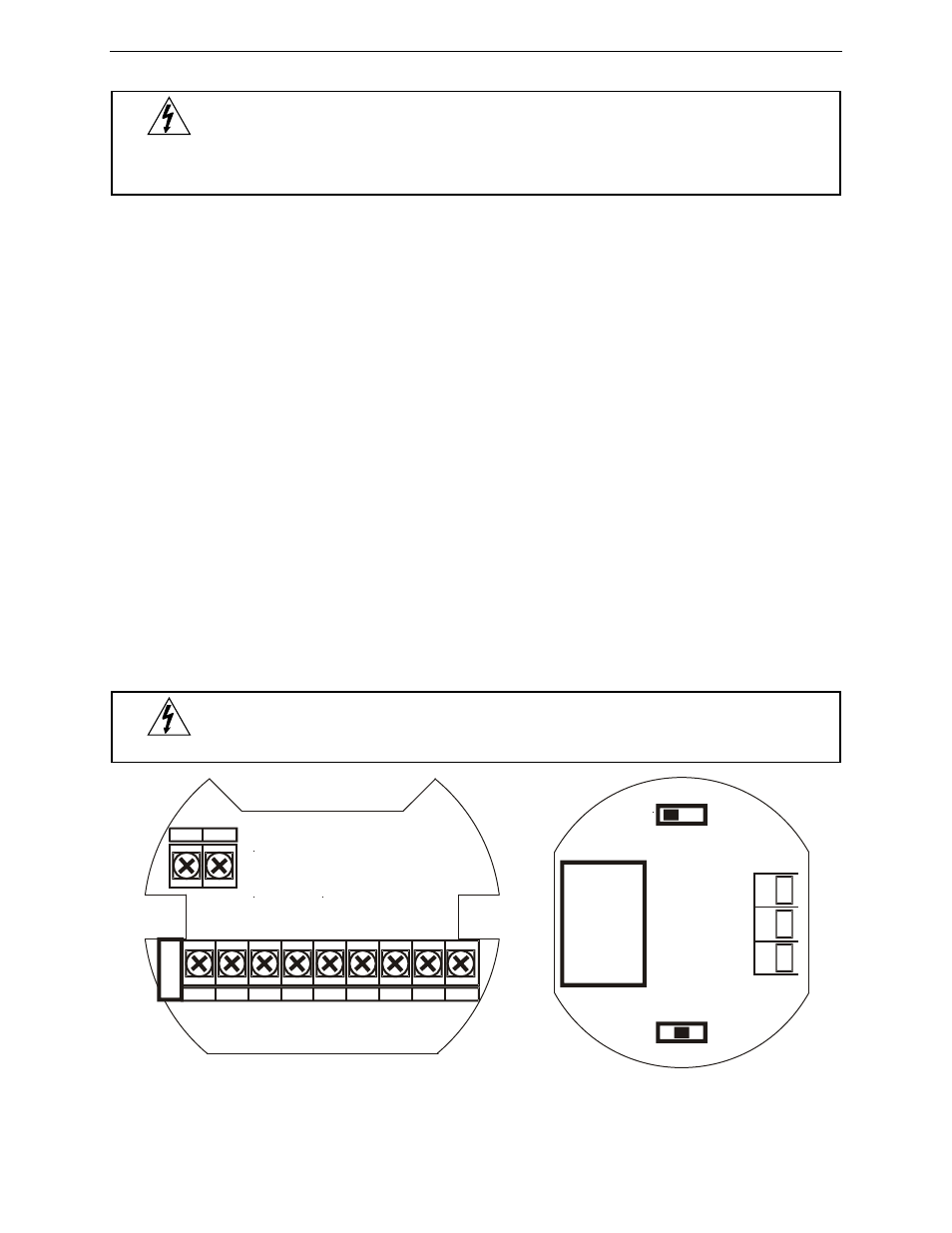
To access the connectors, remove the enclosure cover and unscrew the two captive screws that fasten
the display module into the enclosure. Disconnect the ribbon cable and remove the display module. RS-
485 serial connections are made to a removable terminal block on the back of the display module. Power
and signal connections are made to a barrier terminal connector in the base of the enclosure. Grounding
connections are made to the two ground screws provided on the base – one internal and one external.
Use proper grounding techniques and observe all local and national electric codes.
D+
RS-485 data B (non-inverting) connection
D-
RS-485 data A (inverting) connection
G
RS-485 shield ground connection
P+
DC Power positive terminal connection
COM DC power supply input return/negative, reset contact closure common
RST
Contact closure reset pull-up to 1.8 VDC
S+
Pulse signal input positive terminal connection
S-
Pulse signal input negative terminal connection
OC1+ Open collector output 1 positive terminal
OC1- Open collector output 1 negative terminal
OC2+ Open collector output 2 positive terminal
OC2- Open collector output 2 negative terminal
LP+
4-20 mA transmitter DC power positive terminal connection.
LP-
4-20 mA transmitter regulated current output terminal connection
Refer to Figure 1 for terminal positions.
WARNING
Observe all safety regulations. Electrical wiring should be performed in accordance with
all applicable national, state, and local codes to prevent damage to the scanner and
ensure personnel safety.
Figure 1: Connectors
P+
COM
RST
S+
S-
OC1+ OC1- OC2+ OC2-
LP+
LP-
Boar
d t
o Board
Interc
o
nn
ec
t
Boar
d t
o Board
Interc
o
nn
ec
t
THRU-GLASS
BUTTONS
ON OFF
INPUT LEVEL
mV V ISO
D+
D-
G