ProSoft Technology MVI69-PDPMV1 User Manual
Page 210
Reference MVI69-PDPMV1
♦ CompactLogix or MicroLogix Platform
User Manual
PROFIBUS DPV1 Master
Page 210 of 225
ProSoft Technology, Inc.
July 8, 2011
8 Close the connector housing.
Note: The shielding of both cables is connected internally with the metal housing of the
connector.
9 Complete the Central Shielding Measures (below) and grounding operations
for the shielding before you connect the cable connector to the module.
10 Plug the PROFIBUS DP connector into the module and secure it with the
screws.
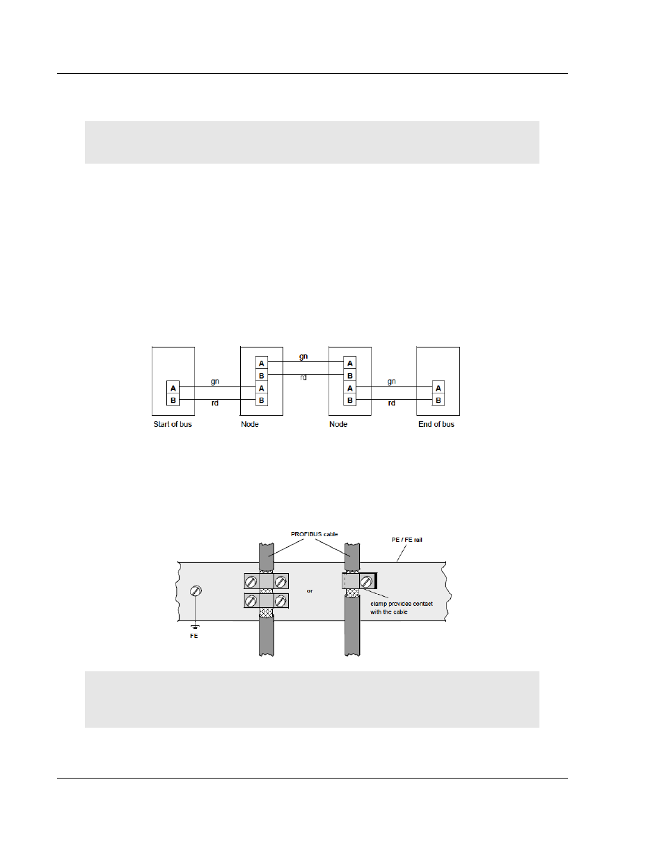
Bus Begin and Bus End
The PROFIBUS connector with termination is required at the beginning and the
end of the bus. These connectors emulate the line impedance.
It is recommended that at least one connector with diagnostics interface is used.
Wiring diagram for a PROFIBUS DP cable
Grounding and Shielding for Systems with Equipotential Bonding
Each cable shield should be galvanically grounded with the earth using FE/PE
grounding clamps immediately after the cable has been connected to the cabinet.
This example indicates the shielding connection from the PROFIBUS cable to the
FE/PE rail.
Note: An equalization current can flow across a shield connected at both ends because of
fluctuations in ground potential. To prevent this, it is imperative that there is potential equalization
between all the attached installation components and devices.